PA76A Cirrus Logic Inc, PA76A Datasheet
PA76A
Specifications of PA76A
Available stocks


Related parts for PA76A


PA76A Summary of contents
Page 1
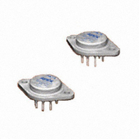
... PA74, PA76, PA74A, PA76A Power Dual Operational Amplifiers FEATURES • LOW COST • WIDE COMMON MODE RANGE — Includes negative supply • WIDE SUPPLY VOLTAGE RANGE Single supply 40V Split supplies: ±2.5V to ±20V • HIGH EFFICIENCY — |Vs–2.2V| at 2.5A typ • HIGH OUTPUT CURRENT — 3A • LOW DISTORTION APPLICATIONS • HALF & FULL BRIDGE MOTOR DRIVERS • AUDIO POWER AMPLIFIER STEREO — 30W RMS per channel BRIDGE — ...
Page 2
... TEMPERATURE RANGE, case Meets full range specifications NOTES: * The specification of PA74A/PA76A is identical to the specification for PA74/PA76 in applicable column to the left. 1. Long term operation at the maximum junction temperature will result in reduced product life. Derate internal power dissipation to achieve high MTTF. 2. Unless otherwise noted, the following conditions apply: ±VS = ±15V 25°C. ...
Page 3
NORMALIZED QUIESCENT CURRENT vs. CASE TEMPERATURE 2.0 1.8 1.5 1.4 1.2 1.0 0.8 0.6 0.4 -80 - ...
Page 4
PA74/76 • PA74A/76A GENERAL Please read Application Note 1 "General Operating Consider- ations" which covers stability, supplies, heatsinking, mounting, SOA interpretation, and specification interpretation. Visit www. Cirrus.com for design tools that help automate tasks such as calculations for stability, internal ...
Page 5
ContACting CiRRUs LogiC sUPPoRt For all Apex Precision Power product questions and inquiries, call toll free 800-546-2739 in North ...