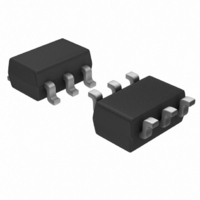
TSV321RILT STMicroelectronics, TSV321RILT Datasheet - Page 2

TSV321RILT
Manufacturer Part Number
TSV321RILT
Description
IC OP AMP SGL I/O R-R LP SOT23-5
Manufacturer
STMicroelectronics
Datasheet
1.TSV321RILT.pdf
(17 pages)
Specifications of TSV321RILT
Amplifier Type
General Purpose
Number Of Circuits
1
Output Type
Rail-to-Rail
Slew Rate
0.6 V/µs
Gain Bandwidth Product
1.4MHz
Current - Input Bias
70nA
Voltage - Input Offset
200µV
Current - Supply
500µA
Current - Output / Channel
80mA
Voltage - Supply, Single/dual (±)
2.5 V ~ 6 V
Operating Temperature
-40°C ~ 125°C
Mounting Type
Surface Mount
Package / Case
SOT-23-6
Number Of Channels
1
Common Mode Rejection Ratio (min)
65 dB
Input Offset Voltage
3 mV
Input Bias Current (max)
130 nA
Operating Supply Voltage
3 V, 5 V
Supply Current
0.835 mA
Maximum Operating Temperature
+ 125 C
Minimum Operating Temperature
- 40 C
Mounting Style
SMD/SMT
Shutdown
No
Supply Voltage (max)
6 V
Supply Voltage (min)
2.5 V
Voltage Gain Db
92 dB
Lead Free Status / RoHS Status
Lead free / RoHS Compliant
-3db Bandwidth
-
Lead Free Status / Rohs Status
Lead free / RoHS Compliant
Other names
497-8164-2
TSV321RILT
TSV321RILT
Available stocks
Company
Part Number
Manufacturer
Quantity
Price
Company:
Part Number:
TSV321RILT
Manufacturer:
RENESAS
Quantity:
120
Part Number:
TSV321RILT
Manufacturer:
ST
Quantity:
20 000
Absolute maximum ratings and operating conditions
1
2/17
Absolute maximum ratings and operating conditions
Table 1.
1. All voltages values, except differential voltage are with respect to network terminal.
2. Differential voltages are the non-inverting input terminal with respect to the inverting input terminal. If
3. Short-circuits can cause excessive heating and destructive dissipation. R
4. Human body model: 100 pF discharged through a 1.5 k Ω resistor between two pins of the device, done for
5. Machine model: a 200 pF capacitor is charged to the specified voltage, then discharged directly between
6. Charged device model: all pins plus package are charged together to the specified voltage and then
7. Short-circuits from the output to V
Symbol
R
ESD
R
V
T
V
must be added to limit input current.
all couples of pin combinations with other pins floating.
two pins of the device with no external series resistor (internal resistor < 5 Ω ), done for all couples of pin
combinations with other pins floating.
discharged directly to the ground.
approximately 80 mA, independent of the magnitude of V
simultaneous short-circuits on all amplifiers.
V
V
T
CC
thja
thjc
id
stg
id
in
j
> ±1 V, the maximum input current must not exceed ±1 mA. When V
Supply voltage
Differential input voltage
Input voltage
Storage temperature
Maximum junction temperature
Thermal resistance junction to ambient
Thermal resistance junction to case
HBM: human body model
MM: machine model
CDM: charged device model
Latch-up immunity
Lead temperature (soldering, 10s)
Output short-circuit duration
Absolute maximum ratings
SOT23-5
SO-8
SO-14
TSSOP8
TSSOP14
MiniSO-8
SOT23-5
SO-8
SO-14
TSSOP8
TSSOP14
MiniSO-8
(1)
(5)
CC
Parameter
can cause excessive heating. The maximum output current is
(2)
(4)
(6)
(3)
(3)
CC
. Destructive dissipation can result from
id
th
> ±1 V, an input series resistor
V
are typical values.
DD
TSV321-TSV358-TSV324
-0.3 to V
-65 to +150
See note
Value
150
250
125
105
120
100
190
200
200
250
1.5
±1
81
40
31
37
32
39
7
2
CC
(7)
+0.3
°C/W
°C/W
Unit
mA
°C
°C
kV
kV
°C
V
V
V
V


