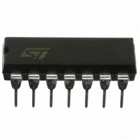
TL074IN STMicroelectronics, TL074IN Datasheet - Page 8

TL074IN
Manufacturer Part Number
TL074IN
Description
IC AMP LN J-FET QUAD OP 14 DIP
Manufacturer
STMicroelectronics
Specifications of TL074IN
Amplifier Type
J-FET
Number Of Circuits
4
Slew Rate
13 V/µs
Gain Bandwidth Product
3MHz
Current - Input Bias
20pA
Voltage - Input Offset
3000µV
Current - Supply
1.4mA
Current - Output / Channel
40mA
Voltage - Supply, Single/dual (±)
6 V ~ 36 V, ±3 V ~ 18 V
Operating Temperature
-40°C ~ 105°C
Mounting Type
Through Hole
Package / Case
14-DIP (0.300", 7.62mm)
Number Of Channels
4
Common Mode Rejection Ratio (min)
80 dB
Input Offset Voltage
10 mV
Input Bias Current (max)
200 pA
Supply Current
2.5 mA
Maximum Power Dissipation
680 mW
Maximum Operating Temperature
+ 105 C
Minimum Operating Temperature
- 40 C
Dual Supply Voltage
+/- 5 V, +/- 9 V, +/- 12 V, +/- 15 V
Maximum Dual Supply Voltage
+/- 18 V
Minimum Dual Supply Voltage
+/- 3 V
Mounting Style
Through Hole
Shutdown
No
Technology
BiFET
Voltage Gain Db
106.02 dB
Bandwidth
3 MHz
Channel Separation
120
Common Mode Rejection Ratio
86
Current, Input Bias
20 pA
Current, Input Offset
5 pA
Current, Output
20 mA
Current, Supply
1.4 mA
Harmonic Distortion
0.01 %
Number Of Amplifiers
Quad
Package Type
DIP-14
Power Dissipation
680 mW
Resistance, Input
10^12 Ohms
Signal Gain
200 V/mV
Temperature, Operating, Range
-40 to +105 °C
Time, Rise
0.1 μs
Voltage, Input
±15 V
Voltage, Noise
15 nV/sqrt Hz
Voltage, Offset
3 mV
Voltage, Supply
6 to 36 V
Lead Free Status / RoHS Status
Lead free / RoHS Compliant
Output Type
-
-3db Bandwidth
-
Lead Free Status / Rohs Status
Lead free / RoHS Compliant
Other names
497-2206-5
Available stocks
Company
Part Number
Manufacturer
Quantity
Price
Part Number:
TL074IN
Manufacturer:
TI/德州仪器
Quantity:
20 000
Electrical characteristics
8/15
Figure 14. Voltage follower large signal pulse
Figure 16. Equivalent input noise voltage
50
70
60
40
30
20
10
0
10
response
versus frequency
40
100
V
FREQUENCY (Hz)
b
400 1k
W
p
V
m
4k
V
A
R
T
CC
amb
V
S
10k
= 10
= 100 Ω
= 15V
= +25˚C
40k 100k
Figure 15. Output voltage versus elapsed time
Figure 17. Total harmonic distortion versus
0.001
0.004
0.04
0.01
0.4
28
24
20
16
12
0.1
-4
1
0
8
4
100
frequency
OVERSHOOT
10%
V
A
V
T
amb
A
V
T
0
V
V
O (rms)
CC
amb
V
O (rms)
CC
= 1
400
= 15V
= 1
= +25˚C
0.1
= 15V
= 6V
= +25˚C
= 6V
90%
t
r
FREQUENCY (Hz)
1k
0.2
TIME ( μ s)
0.3
4k
0.4
V
10k
R
T
amb
CC
L
0.5
= 2k Ω
= 15V
= +25˚C
40k
0.6
TL074
0.7
100k


