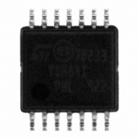
TSH84IPT STMicroelectronics, TSH84IPT Datasheet - Page 19

TSH84IPT
Manufacturer Part Number
TSH84IPT
Description
IC OPAMP R-R WIDE 14TSSOP
Manufacturer
STMicroelectronics
Datasheet
1.TSH80IDT.pdf
(27 pages)
Specifications of TSH84IPT
Amplifier Type
General Purpose
Number Of Circuits
4
Output Type
Rail-to-Rail
Slew Rate
118 V/µs
Gain Bandwidth Product
65MHz
-3db Bandwidth
100MHz
Current - Input Bias
6µA
Voltage - Input Offset
800µV
Current - Supply
9.8mA
Current - Output / Channel
55mA
Voltage - Supply, Single/dual (±)
4.5 V ~ 12 V, ±2.25 V ~ 6 V
Operating Temperature
-40°C ~ 85°C
Mounting Type
Surface Mount
Package / Case
14-TSSOP
Number Of Channels
4
Voltage Gain Db
84 dB
Common Mode Rejection Ratio (min)
72 dB
Input Offset Voltage
10 mV
Operating Supply Voltage
5 V, 9 V
Supply Current
42 mA
Maximum Operating Temperature
+ 85 C
Mounting Style
SMD/SMT
Maximum Dual Supply Voltage
+/- 6 V
Minimum Operating Temperature
- 40 C
Lead Free Status / RoHS Status
Lead free / RoHS Compliant
Other names
497-8926-2
Available stocks
Company
Part Number
Manufacturer
Quantity
Price
TSH80, TSH81, TSH82, TSH84
4
Precautions on asymmetrical supply operation
The TSH8x can be used with either a dual or a single supply. If a single supply is used, the
inputs are biased to the mid-supply voltage (+V
designed so as to reject any noise present on the supply rail.
As the bias current is 15 µA, you should use a high resistance R1 (approximately 10 kΩ) to
avoid introducing an offset mismatch at the amplifier’s inputs.
Figure 33. Asymmetrical supply schematic diagram
C1, C2, C3 are bypass capacitors intended to filter perturbations from V
capacitor values are appropriate.
R2 and R3 are such that the current through them must be superior to 100 times the bias
current. Therefore, you could use the following resistance values.
C
C
frequency obtained is lower than 10 Hz.
Figure 34. Use of the TSH8x in a gain = -1 configuration
in
out
and C
). With R1 = 10 kΩ , R
C1 = 100 nF and C2 = C3 = 100 µF
R2 = R3 = 4.7 kΩ
out
are chosen to filter the DC signal by the low pass filters (R1, C
IN
IN
out
Cin
Cin
R1
R1
= R
Doc ID 9413 Rev 5
R2
R3
R2
R3
L
= 150 Ω, and C
C1
C1
Vcc+
Vcc+
Precautions on asymmetrical supply operation
C2
C2
C3
C3
1 k
CC
in
/2). This bias network must be carefully
R4
+
-
+
= 2 µF, C
-
1 k
Cf
Cf
R5
Cout
Cout
out
AM00845
AM00846
OUT
OUT
= 220 µF the cutoff
RL
RL
CC
. The following
in
) and (R
out
19/27
,


