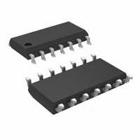
LMV324MX/NOPB National Semiconductor, LMV324MX/NOPB Datasheet - Page 19

LMV324MX/NOPB
Manufacturer Part Number
LMV324MX/NOPB
Description
IC OP AMP QUAD LOW V R-R 14-SOIC
Manufacturer
National Semiconductor
Datasheet
1.LMV321M5NOPB.pdf
(28 pages)
Specifications of LMV324MX/NOPB
Amplifier Type
General Purpose
Number Of Circuits
4
Output Type
Rail-to-Rail
Slew Rate
1 V/µs
Gain Bandwidth Product
1MHz
Current - Input Bias
15nA
Voltage - Input Offset
1700µV
Current - Supply
410µA
Current - Output / Channel
160mA
Voltage - Supply, Single/dual (±)
2.7 V ~ 5.5 V
Operating Temperature
-40°C ~ 85°C
Mounting Type
Surface Mount
Package / Case
14-SOIC (3.9mm Width), 14-SOL
Lead Free Status / RoHS Status
Lead free / RoHS Compliant
-3db Bandwidth
-
Other names
LMV324MX
LMV324MXTR
LMV324MXTR
Available stocks
Company
Part Number
Manufacturer
Quantity
Price
Company:
Part Number:
LMV324MX/NOPB
Manufacturer:
TI
Quantity:
10 495
Part Number:
LMV324MX/NOPB
Manufacturer:
TI/德州仪器
Quantity:
20 000
When the output voltage V
pacitor C is charged toward V
across C rises exponentially with a time constant τ = R
this voltage is applied to the inverting input of the op amp.
Meanwhile, the voltage at the non-inverting input is set at the
positive threshold voltage (V
pacitor voltage continually increases until it reaches V
which point the output of the generator will switch to its low,
V
input is switched to the negative threshold voltage (V
the generator. The capacitor then starts to discharge toward
V
When the capacitor voltage reaches V
pulse generator switches to V
charge, and the cycle repeats itself.
As shown in the waveforms in
(T
(T
to have different frequencies and pulse width by selecting dif-
ferent capacitor value and resistor values.
Figure 18
charge and discharge paths. The capacitor is charged
through R
OL
OL
1
2
) is set by R
) is set by R
FIGURE 17. Waveforms of the Circuit in Figure 16
which 0V is in this case. The voltage at the non-inverting
exponentially through R
1
shows another pulse generator, with separate
and is discharged through R
1
, C and V
2
, C and V
OL
. This pulse generator can be made
OH
O
1
, and the time between pulses
is first at its high, V
TH+
, with a time constant τ = R
OH
OH
) of the generator. The ca-
Figure
. The capacitor starts to
through R
TH−
2
17, the pulse width
.
, the output of the
2
. The voltage
OH
, the ca-
2
C, and
TH−
TH+
10006086
) of
, at
1
C.
19
Figure 19
charging and discharging the capacitor.
CURRENT SOURCE AND SINK
The LMV321/LMV358/LMV324 can be used in feedback
loops which regulate the current in external PNP transistors
to provide current sources or in external NPN transistors to
provide current sinks.
Fixed Current Source
A multiple fixed current source is shown in
age (V
voltage divider (R
cause the voltage drop across R
controls the emitter current of transistor Q
the base current of Q
is available out of the collector of Q
Large input resistors can be used to reduce current loss and
a Darlington connection can be used to reduce errors due to
the β of Q
The resistor, R
Q
2
either above or below the 1 mA reference value.
REF
1
is a squarewave generator with the same path for
.
FIGURE 19. Squarewave Generator
= 2V) is established across resistor R
2
FIGURE 18. Pulse Generator
, can be used to scale the collector current of
3
and R
1
and Q
4
). Negative feedback is used to
2
, essentially this same current
1
to be equal to V
1
.
1
Figure
and if we neglect
www.national.com
10006076
20. A volt-
REF
3
10006077
by the
. This


