LME49720HA/NOPB National Semiconductor, LME49720HA/NOPB Datasheet
LME49720HA/NOPB
Specifications of LME49720HA/NOPB
LME49720HA
Available stocks


Related parts for LME49720HA/NOPB

LME49720HA/NOPB Summary of contents
Page 1
... Key Specifications ■ Power Supply Voltage Range ■ THD 1kHz) V OUT RMS IN Typical Application © 2007 National Semiconductor Corporation R = 2kΩ 600Ω ■ Input Noise Density ■ Slew Rate ■ Gain Bandwidth Product ■ ...
Page 2
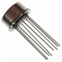
Connection Diagrams www.national.com Order Number LME49720MA See NS Package Number — M08A Order Number LME49720NA See NS Package Number — N08E Metal Can Order Number LME49720HA See NS Package Number — H08C 2 30003855 300038f3 ...
Page 3
... Absolute Maximum Ratings If Military/Aerospace specified devices are required, please contact the National Semiconductor Sales Office/ Distributors for availability and specifications. Power Supply Voltage ( Storage Temperature Input Voltage (V-) Output Short Circuit (Note 3) Power Dissipation ESD Susceptibility (Note 4) ESD Susceptibility (Note 5) Electrical Characteristics for the LME49720 V = ± ...
Page 4
Symbol Parameter A Open Loop Voltage Gain VOL V Maximum Output Voltage Swing OUTMAX I Output Current OUT I Instantaneous Short Circuit Current OUT-CC R Output Impedance OUT C Capacitive Load Drive Overshoot LOAD I Total Quiescent Current S Note ...
Page 5
Typical Performance Characteristics THD+N vs Output Voltage V = 15V –15V 2kΩ L THD+N vs Output Voltage V = 17V –17V 2kΩ L THD+N vs Output Voltage V ...
Page 6
THD+N vs Output Voltage V = 17V 600Ω THD+N vs Output Voltage V = 15V 10kΩ L THD+N vs Output Voltage V = 17V ...
Page 7
THD+N vs Frequency V = 15V –15V OUT RMS R = 2kΩ L 30003863 THD+N vs Frequency V = 17V –17V OUT RMS R = 2kΩ ...
Page 8
THD+N vs Frequency V = 15V –15V 10kΩ L THD+N vs Frequency V = 17V –17V 10kΩ L IMD vs Output Voltage V = 12V, V ...
Page 9
IMD vs Output Voltage V = 17V –17V 2kΩ L 300038e7 IMD vs Output Voltage V = 12V –12V 600Ω 300038e0 IMD vs Output Voltage V = ...
Page 10
IMD vs Output Voltage V = 12V 10kΩ L IMD vs Output Voltage V = 2.5V 10kΩ L Current Noise Density vs Frequency www.national.com = –12V 300038f0 = –2.5V 300038l6 ...
Page 11
Crosstalk vs Frequency V = 15V –15V 10V CC EE OUT RMS A = 0dB 2kΩ 300038c9 Crosstalk vs Frequency V = 12V –12V 10V CC EE OUT ...
Page 12
Crosstalk vs Frequency V = 15V –15V 0dB Crosstalk vs Frequency V = 12V –12V 0dB Crosstalk vs Frequency V ...
Page 13
Crosstalk vs Frequency V = 2.5V –2.5V OUT RMS = 600Ω 0dB 300038d2 Crosstalk vs Frequency V = 15V –15V 10V CC EE OUT ...
Page 14
Crosstalk vs Frequency V = 17V –17V 0dB PSRR+ vs Frequency V = 15V 10kΩ 200kHz PSRR+ vs Frequency V = ...
Page 15
PSRR+ vs Frequency V = 15V –15V 600Ω 200kHz 200mVpp L RIPPLE 300038p1 PSRR+ vs Frequency V = 12V –12V 10kΩ 200kHz, ...
Page 16
PSRR+ vs Frequency V = 12V 600Ω 200kHz PSRR+ vs Frequency V = 17V 10kΩ 200kHz PSRR+ vs Frequency V = 17V, ...
Page 17
PSRR+ vs Frequency V = 17V –17V 600Ω 200kHz 200mVpp L RIPPLE 300038q9 PSRR+ vs Frequency V = 2.5V –2. 10kΩ 200kHz, ...
Page 18
PSRR+ vs Frequency V = 2.5V 600Ω 200kHz CMRR vs Frequency V = 15V 2kΩ L CMRR vs Frequency V = 17V ...
Page 19
CMRR vs Frequency V = 15V –15V 600Ω 300038o9 CMRR vs Frequency V = 17V –17V 600Ω 300038g5 CMRR vs Frequency V = 15V ...
Page 20
CMRR vs Frequency V = 17V 10kΩ L Output Voltage vs Load Resistance V = 15V THD Output Voltage vs Load Resistance V = 17V THD+N = ...
Page 21
Output Voltage vs Supply Voltage R = 2kΩ, THD 300038j9 Output Voltage vs Supply Voltage R = 10kΩ, THD 300038k0 Supply Current vs Supply Voltage = 600Ω 300038j5 Output Voltage vs Supply ...
Page 22
Full Power Bandwidth vs Frequency Small-Signal Transient Response 10pF V L www.national.com Gain Phase vs Frequency 300038j0 Small-Signal Transient Response 300038i7 22 300038j1 100pF V L 300038i8 ...
Page 23
Application Information DISTORTION MEASUREMENTS The vanishingly low residual distortion produced by LME49720 is below the capabilities of all commercially avail- able equipment. This makes distortion measurements just slightly more difficult than simply connecting a distortion me- ter to the amplifier’s ...
Page 24
The LME49720 is a high speed op amp with excellent phase margin and stability. Capacitive loads up to 100pF will cause little change in the phase characteristics of the amplifiers and are therefore allowable. Capacitive loads greater than 100pF must ...
Page 25
TYPICAL APPLICATIONS NAB Preamp kHz = 0.38 μ Weighted Balanced to Single Ended Converter V = V1–V2 O 30003830 − V3 − 30003832 ...
Page 26
Second Order High Pass Filter (Butterworth) Illustration kHz 0 Illustration kHz 10 www.national.com Second Order Low Pass Filter 30003835 Illustration kHz ...
Page 27
Channel Panning Circuit (Pan Pot) 30003839 AC/DC Converter Line Driver Tone Control 300038p0 27 30003838 30003840 www.national.com ...
Page 28
Illustration is Hz 320 =11 kHz 1.1 kHz 0.33 μ S kHz A ...
Page 29
Illustration is 101(V2 − V1) Balanced Input Mic Amp 29 30003843 www.national.com ...
Page 30
... Note 9: At volume of change = ±12 dB 1.7 Reference: “AUDIO/RADIO HANDBOOK”, National Semiconductor, 1980, Page 2–61 www.national.com 10 Band Graphic Equalizer fo (Hz 0.12μF 4.7μF 32 75kΩ 0.056μF 3.3μF 64 68kΩ 0.033μF 1.5μF 125 62kΩ ...
Page 31
Revision History Rev Date 1.0 03/30/07 1.1 05/03/07 1.2 10/22/07 Description Initial release. Put the “general note” under the EC table. Replaced all the PSRR curves. 31 www.national.com ...
Page 32
Physical Dimensions www.national.com inches (millimeters) unless otherwise noted Narrow SOIC Package Order Number LME49720MA NS Package Number M08A Dual-In-Line Package Order Number LME49720NA NS Package Number N08E 32 ...
Page 33
TO-99 Metal Can Package Order Number LME49720HA NS Package Number H08C 33 www.national.com ...
Page 34
... National Semiconductor and the National Semiconductor logo are registered trademarks of National Semiconductor Corporation. All other brand or product names may be trademarks or registered trademarks of their respective holders. ...