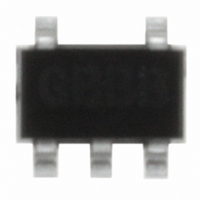
NJM2711F-TE1# NJR, NJM2711F-TE1# Datasheet - Page 3

NJM2711F-TE1#
Manufacturer Part Number
NJM2711F-TE1#
Description
IC OPAMP ULTRA HI-SPD MTP5
Manufacturer
NJR
Datasheet
1.NJM2711F-TE1.pdf
(8 pages)
Specifications of NJM2711F-TE1#
Amplifier Type
General Purpose
Number Of Circuits
1
Slew Rate
260 V/µs
Gain Bandwidth Product
1GHz
Current - Input Bias
2µA
Voltage - Input Offset
2000µV
Current - Supply
1.9mA
Voltage - Supply, Single/dual (±)
±2 V ~ 4.5 V
Operating Temperature
-40°C ~ 85°C
Mounting Type
Surface Mount
Package / Case
SOT-23-5, SC-74A, SOT-25
Lead Free Status / RoHS Status
Lead free / RoHS Compliant
Output Type
-
Current - Output / Channel
-
-3db Bandwidth
-
Other names
NJM#2711F-TE1
NJM#2711F-TE1TR
NJM#2711F-TE1TR
NJM2711F-TE1#TR
NJM#2711F-TE1TR
NJM#2711F-TE1TR
NJM2711F-TE1#TR
non-inverting amplifier
inverting amplifier
1.The closed gain should be 6dB or higher to prevent the oscillation.
2.When the closed gain is lower than 20dB, use a compensation capacitor (CF: about 5pF),
3.Recommended feedback resistor is less than 2k-ohom to keep the flatness of the frequency response.
4.Minimize the load capacitor for the better performance.
1.When the closed gain is lower than 20dB, use a compensation capacitor
2.Minimize the feedback resistor to keep the frequency response and the slew rate.
3.Total load capacitance should be not more than 100pF.
Note:
Unity gain follower application may cause the oscillation.
parallel with the feedback resistor RF to avoid oscillation.
A large load capacitor CL reduces the frequency response and causes oscillation or ringing.
(CF; recommended from 1pF to 5pF), parallel with the feedback resistor RF to avoid oscillation.
(recommended about 1k-ohom)
The proper compensation capacitor CF can counteract oscillation even with a large feedback resistor RF.
The oscillation margin may be affected by the total load capacitance.
inverting amplifier
non-inverting amplifier
RG
RG
CF
RF
DUT
DUT
RF
CF
CL
CL
RL
RL
NJM2711
- 3 -


