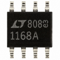
LT1168ACS8#PBF Linear Technology, LT1168ACS8#PBF Datasheet - Page 16

LT1168ACS8#PBF
Manufacturer Part Number
LT1168ACS8#PBF
Description
IC AMP INSTR PREC PROG 8-SOIC
Manufacturer
Linear Technology
Specifications of LT1168ACS8#PBF
Amplifier Type
Instrumentation
Number Of Circuits
1
Slew Rate
0.5 V/µs
Gain Bandwidth Product
400kHz
Current - Input Bias
40pA
Voltage - Input Offset
15µV
Current - Supply
350µA
Current - Output / Channel
32mA
Voltage - Supply, Single/dual (±)
4.6 V ~ 36 V, ±2.3 V ~ 18 V
Operating Temperature
0°C ~ 70°C
Mounting Type
Surface Mount
Package / Case
8-SOIC (3.9mm Width)
Lead Free Status / RoHS Status
Lead free / RoHS Compliant
Output Type
-
-3db Bandwidth
-
Available stocks
Company
Part Number
Manufacturer
Quantity
Price
APPLICATIO S I FOR ATIO
LT1168
a ground for the common mode signal. C1 was chosen to
maintain the stability of the patient ground. The LT1168’s
high CMRR ensures that the desired differential signal is
amplified and unwanted common mode signals are at-
tenuated. Since the DC portion of the signal is not impor-
tant, R6 and C2 make up a 0.3Hz highpass filter. The AC
signal at LT1112’s Pin 5 is amplified by a gain of 101 set
by R7/R8 +1. The parallel combination of C3 and R7 form
a lowpass filter that decreases this gain at frequencies
above 1kHz. The ability to operate at ±3V on 350µA of
supply current makes the LT1168 ideal for battery-pow-
ered applications. Total supply current for this application
is 1.05mA. Proper safeguards, such as isolation, must be
added to this circuit to protect the patient from possible
harm.
16
Figure 9. Precision Temperature Without Precision Resistors
LT1634-1.25
THERMISTOR
PRECISION
PATIENT
GND
–IN
+IN
R
T
–15V
22k
PATIENT/CIRCUIT
PROTECTION/ISOLATION
U
3
8
1
2
1
0.01µF
+
–
C1
–15V
LT1168
15V
U
1M
R2
LT1112
7
4
1/2
1168 F09
12k
R1
–
+
REF
3
2
5
W
6
R3
30k
R4
30k
V
OUT
A
POLE AT 1kHz
V
Figure 8. Nerve Impulse Amplifier
= 101
= 1.25 •
R
6k
G
U
1
3
8
2
+
–
49.4kΩ
R
LT1168
T
G = 10
–3V
3V
4
7
Low I
Dissipation
The LT1168’s low supply current, low supply voltage
operation and low input bias currents allow it to fit nicely
into battery-powered applications. Low overall power
dissipation necessitates using higher impedance bridges.
The single supply pressure monitor application on the
front of this data sheet, shows the LT1168 connected to
the differential output of a 3.5k bridge. The picoampere
input bias currents keep the error caused by offset current
to a negligible level. The LT1112 level shifts the LT1168’s
reference pin and the ADC’s analog ground pins above
ground. The LT1168’s and LT1112’s combined power
dissipation is still less than the bridge’s. This circuit’s total
supply current is just 2.2mA.
5
Figure 10. Response of Figure 9 for Various Thermistors
6
B
Favors High Impedance Bridges, Lowers
0.47µF
14
12
10
8
6
4
2
0
C2
–40
YSI #44006
–20
THERMOMETRICS
0.3Hz
HIGHPASS
R6
1M
DC95F103W
100Ω
R8
0
TEMPERATURE (°C)
20
5
6
+
–
40
LT1112
1/2
–3V
3V
15nF
60
DC95G104Z
C3
METRICS
4
THERMO
8
YSI #44011
80 100
10k
R7
7
1168 F10
120
OUTPUT
1V/mV
1168 F08
1168fa


