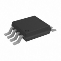
ADA4841-2YRMZ Analog Devices Inc, ADA4841-2YRMZ Datasheet - Page 16

ADA4841-2YRMZ
Manufacturer Part Number
ADA4841-2YRMZ
Description
IC OPAMP VF R-R DUAL LP LN 8MSOP
Manufacturer
Analog Devices Inc
Datasheet
1.ADA4841-1YRZ-R7.pdf
(20 pages)
Specifications of ADA4841-2YRMZ
Slew Rate
13 V/µs
Amplifier Type
Voltage Feedback
Number Of Circuits
2
Output Type
Rail-to-Rail
-3db Bandwidth
80MHz
Current - Input Bias
3µA
Voltage - Input Offset
40µV
Current - Supply
1.5mA
Current - Output / Channel
60mA
Voltage - Supply, Single/dual (±)
2.7 V ~ 12 V, ±1.35 V ~ 6 V
Operating Temperature
-40°C ~ 125°C
Mounting Type
Surface Mount
Package / Case
8-MSOP, Micro8™, 8-uMAX, 8-uSOP,
Op Amp Type
Low Power
No. Of Amplifiers
2
Bandwidth
80MHz
Supply Voltage Range
2.7V To 12V
Amplifier Case Style
MSOP
No. Of Pins
8
Operating Temperature Range
-40°C To +125°C
Lead Free Status / RoHS Status
Lead free / RoHS Compliant
Gain Bandwidth Product
-
Lead Free Status / RoHS Status
Lead free / RoHS Compliant, Lead free / RoHS Compliant
Available stocks
Company
Part Number
Manufacturer
Quantity
Price
Company:
Part Number:
ADA4841-2YRMZ
Manufacturer:
ADI
Quantity:
6
Part Number:
ADA4841-2YRMZ
Manufacturer:
ADI/亚德诺
Quantity:
20 000
Part Number:
ADA4841-2YRMZ-R7
Manufacturer:
ADI原装
Quantity:
20 000
ADA4841-1/ADA4841-2
POWER-DOWN OPERATION
Figure 48 shows the ADA4841-1 power-down circuitry. If the
POWER DOWN pin is left unconnected, then the base of the
input PNP transistor is pulled high through the internal pull-up
resistor to the positive supply, and the part is turned on. Pulling
the POWER DOWN pin approximately 1.7 V below the positive
supply turns the part off, reducing the supply current to
approximately 40 μA.
VCC
VEE
Figure 48. POWER DOWN Circuit
I
BIAS
AMPLIFIER
BIAS
TO
ESD
ESD
POWER DOWN
Rev. E | Page 16 of 20
The POWER DOWN pin is protected with ESD clamps,
as shown in
cause these diodes to conduct. The guidelines for limiting the
overload current in the input protection section should also be
followed for the
Figure 48
POWER DOWN pin.
. Voltages beyond the power supplies


