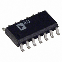
OP484FS Analog Devices Inc, OP484FS Datasheet - Page 2

OP484FS
Manufacturer Part Number
OP484FS
Description
IC OPAMP GP R-R 4.25MHZ 14SOIC
Manufacturer
Analog Devices Inc
Datasheet
1.OP184FSZ.pdf
(24 pages)
Specifications of OP484FS
Slew Rate
4 V/µs
Rohs Status
RoHS non-compliant
Amplifier Type
General Purpose
Number Of Circuits
4
Output Type
Rail-to-Rail
Gain Bandwidth Product
4.25MHz
Current - Input Bias
80nA
Voltage - Input Offset
250µV
Current - Supply
2.25mA
Current - Output / Channel
10mA
Voltage - Supply, Single/dual (±)
3 V ~ 36 V, ±1.5 V ~ 18 V
Operating Temperature
-40°C ~ 125°C
Mounting Type
Surface Mount
Package / Case
14-SOIC (3.9mm Width), 14-SOL
No. Of Amplifiers
4
Bandwidth
4.25MHz
No. Of Pins
14
Peak Reflow Compatible (260 C)
No
Input Bias Current
80nA
Input Offset Voltage Max
0.15mV
Leaded Process Compatible
No
-3db Bandwidth
-
Lead Free Status / RoHS Status
Contains lead / RoHS non-compliant
Available stocks
Company
Part Number
Manufacturer
Quantity
Price
Part Number:
OP484FS
Manufacturer:
ADI/亚德诺
Quantity:
20 000
Part Number:
OP484FSZ
Manufacturer:
ADI/亚德诺
Quantity:
20 000
Company:
Part Number:
OP484FSZ-REEL
Manufacturer:
ST
Quantity:
9 121
Part Number:
OP484FSZ-REEL7
Manufacturer:
ADI/亚德诺
Quantity:
20 000
OP184/OP284/OP484
TABLE OF CONTENTS
Features .............................................................................................. 1
Applications....................................................................................... 1
General Description ......................................................................... 1
Pin Configurations ........................................................................... 1
Revision History ............................................................................... 2
Specifications..................................................................................... 3
Absolute Maximum Ratings............................................................ 6
Typical Performance Characteristics ............................................. 7
Applications Information .............................................................. 14
REVISION HISTORY
10/10—Rev. H to Rev I
Change to Output Characteristics, Output Voltage High
Parameter, Table 2............................................................................. 3
Change to Output Characteristics, Output Voltage High
Parameter, Table 3............................................................................. 4
7/10—Rev. G to Rev. H
Added Table 1.................................................................................... 1
2/09—Rev. F to Rev. G
Change to Large Signal Voltage Gain, Table 3 .............................. 5
Updated Outline Dimensions ....................................................... 21
Changes to Ordering Guide .......................................................... 22
9/08—Rev. E to Rev. F
Changes to General Description .................................................... 1
Changes to Figure 4.......................................................................... 6
Changes to Low Dropout Regulator with Current Limiting .... 20
7/08—Rev. D to Rev. E
Changes to Figure 1.......................................................................... 1
Changes to Figure 12........................................................................ 8
Changes to Figure 36 and Figure 37............................................. 12
Changes to Designing Low Noise Circuits in Single-Supply
Applications Section....................................................................... 15
Updated Outline Dimensions ....................................................... 21
Changes to Ordering Guide .......................................................... 22
Electrical Characteristics............................................................. 3
Thermal Resistance ...................................................................... 6
ESD Caution.................................................................................. 6
Functional Description.............................................................. 14
Input Overvoltage Protection ................................................... 14
Rev. I | Page 2 of 24
Outline Dimensions ....................................................................... 21
4/06—Rev. C to Rev. D
Changes to Table 1.............................................................................3
Changes to Table 2.............................................................................4
Changes to Table 3.............................................................................5
Deleted Reference to 1993 System Applications Guide .............. 15
3/06—Rev. B to Rev. C
Changes to Figure 1 Caption............................................................1
Changes to Table 1.............................................................................3
Changes to Table 2.............................................................................4
Changes to Table 3.............................................................................5
Changes to Table 4.............................................................................6
Changes to Figure 5 through Figure 9 ............................................7
Changes to Functional Description Section ............................... 14
Deleted SPICE Macro Model........................................................ 21
Updated Outline Dimensions....................................................... 21
Changes to Ordering Guide .......................................................... 22
9/02—Rev. A to Rev. B
Changes to Pin Configurations .......................................................1
Changes to Specifications, Input Bias Current Maximum...........2
Changes to Ordering Guide .............................................................5
Updated Outline Dimensions....................................................... 19
6/02—Rev. 0 to Rev. A
10/96—Revision 0: Initial Version
Output Phase Reversal............................................................... 15
Designing Low Noise Circuits in Single-Supply
Applications ................................................................................ 15
Overdrive Recovery ................................................................... 16
Single-Supply, 3 V Instrumentation Amplifier ...................... 16
2.5 V Reference from a 3 V Supply .......................................... 17
5 V Only, 12-Bit DAC Swings Rail-to-Rail ............................. 17
High-Side Current Monitor ...................................................... 18
Capacitive Load Drive Capability ............................................ 18
Low Dropout Regulator with Current Limiting..................... 18
3 V, 50 Hz/60 Hz Active Notch Filter with False Ground..... 20
Ordering Guide .......................................................................... 22


