PA96CE Cirrus Logic Inc, PA96CE Datasheet - Page 4
PA96CE
Manufacturer Part Number
PA96CE
Description
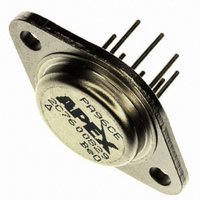
IC PWR AMP 300V 1.5A 8PIN TO3
Manufacturer
Cirrus Logic Inc
Series
Apex Precision Power™r
Datasheet
1.PA96CE.pdf
(5 pages)
Specifications of PA96CE
Amplifier Type
Power
Number Of Circuits
1
Slew Rate
250 V/µs
Gain Bandwidth Product
175MHz
Current - Input Bias
200pA
Voltage - Input Offset
1000µV
Current - Supply
30mA
Current - Output / Channel
1.5A
Voltage - Supply, Single/dual (±)
30 V ~ 300 V, ±15 V ~ 150 V
Operating Temperature
-25°C ~ 85°C
Mounting Type
Through Hole
Package / Case
TO-3-8
Number Of Channels
1
Voltage Gain Db
114 dB
Common Mode Rejection Ratio (min)
92 dB
Input Offset Voltage
5 mV
Maximum Operating Temperature
+ 85 C
Mounting Style
Through Hole
Maximum Dual Supply Voltage
+/- 150 V
Minimum Operating Temperature
- 25 C
Lead Free Status / RoHS Status
Lead free / RoHS Compliant
Output Type
-
-3db Bandwidth
-
Lead Free Status / Rohs Status
Details
Other names
598-1449
PA96
PA96
PA96CE
PA96
PA96
PA96CE
Available stocks
Company
Part Number
Manufacturer
Quantity
Price
Company:

Part Number:
PA96CE
Manufacturer:
SANEKN
Quantity:
21 500
Company:
Part Number:
PA96CE
Manufacturer:
Cirrus Logic Inc
Quantity:
135
Part Number:
PA96CE
Manufacturer:
APEX
Quantity:
20 000


PA96
GENERAL
siderations” which covers stability, supplies, heat sinking,
mounting, current limit, SOA interpretation, and specification
interpretation. Visit www.Cirrus.com for design tools that help
automate tasks such as calculations for stability, internal power
dissipation, current limit, heat sink selection, Apex Precision
Power’s Application Notes library, Technical Seminar Workbook,
and Evaluation Kits.
SPECIAL PRECAUTIONS
delivers amperes of current. Precautions should be taken for
the safety of the user and the amplifier.
to rail, the differential input voltage must not exceed ±15 V.
caused by disconnecting a signal source , typical power turn
on transients can destroy the amplifier.
transient can be generated if the slew rate of the input is greater
than that of the voltage follower.
to back diodes as shown below.
turn off the supplies and let them bleed to low voltage before
installing each new value. Otherwise internal current pulses of
up to 3 amps can be induced. Also, do you want your fingers
around 300V?
applied to the compensation capacitor. A 400V COG or Mica
capacitor is recommended.
POWER BANDWIDTH
The slew time is determined by the compensation capacitor,
load, and internal device capacitance; it is independent of
closed loop gain. The uncompensated power bandwidth is
typically 100kHz for a 250Vp-p output signal into 100
cally increases to above 300KHz with no load.
4
Please read Application Note 1 “General Operating Con-
The PA96 operates with up 300V rail to rail voltage, and
Although the non-operating common mode input range is rail
Therefore; if the feedback ratio is less than 10, even if
Similarly in a voltage follower application a large differential
Therefore it is prudent to clamp the input with series back
If experimentally optimizing the compensation capacitor,
Essentially the full rail to rail power supply voltage may be
The power bandwidth is 1/(π x the negative edge slew time).
1N4148
1N4148
1N4148
1N4148
PA96
Ω
. It typi-
P r o d u c t I n n o v a t i o n F r o m
COMPENSATION TABLE
capacitor values vs. gain. These values will typically result in
less than 2% overshoot and a -3db small signal bandwidth of
greater than 1MHz, except under operating conditions where
uncompensated gain bandwidth is too low to support a 1MHz
bandwidth. (See gain bandwidth vs. Plus power supply curves).
Note that other factors such as capacitance in parallel with
the feedback resistor may reduce circuit bandwidth from that
determined from the gain bandwidth curve.
CURRENT LIMIT
be connected as shown in the external connections diagram.
The minimum value is 0.2Ω, with a maximum practical value
of 100Ω. For optimum reliability the resistor should be set as
high as possible. The value is calculated as I
that the 0.68V is reduced by 2mV every °C rise in temperature.
is exceeded on a continuous basis. As an example if the current
limit was set at 1.5A and the supply was at 150V, a short to
ground would produce 225 watts internal dissipation, greatly
exceeding the 83 watt steady state SOA rating.
plifier may oscillate at a low level when current limit is active,
even though the amplifier is stable otherwise. The current
will be limited to the programmed value in this situation. To
minimize such occurrences, use a non-reactive resistor to
program current limit.
The following table tabulates recommended compensation
For proper operation the current limit resistor, Rcl, must
Also note that the current limit can be set such that the SOA
Under some conditions of load and compensation the am-
330 pf
150pf
150pf
None
None
51pf
33pf
22pf
51pf
33pf
22pf
10pf
10pf
5pf
5pf
Cc
Cc
From
From
100
100
10
20
50
10
20
50
1
2
5
1
2
3
6
Inverting Gain
Non-Inverting Gain
100
100
To
10
20
50
up
To
10
20
50
up
2
5
2
3
6
L
= 0.68V/Rcl. Note
PA96U
Related parts for PA96CE
Image
Part Number
Description
Manufacturer
Datasheet
Request
R

Part Number:
Description:
Development Kit
Manufacturer:
Cirrus Logic Inc
Datasheet:
Part Number:
Description:
Development Kit
Manufacturer:
Cirrus Logic Inc
Datasheet:


Part Number:
Description:
High-efficiency PFC + Fluorescent Lamp Driver Reference Design
Manufacturer:
Cirrus Logic Inc
Datasheet:
Part Number:
Description:
Development Kit
Manufacturer:
Cirrus Logic Inc
Datasheet:
Part Number:
Description:
Development Kit
Manufacturer:
Cirrus Logic Inc
Datasheet:

Part Number:
Description:
Development Kit
Manufacturer:
Cirrus Logic Inc
Datasheet:
Part Number:
Description:
Development Kit
Manufacturer:
Cirrus Logic Inc
Datasheet:
Part Number:
Description:
Development Kit
Manufacturer:
Cirrus Logic Inc
Datasheet:
Part Number:
Description:
Development Kit
Manufacturer:
Cirrus Logic Inc
Datasheet:

Part Number:
Description:
EVALUATION BOARD FOR CS8427
Manufacturer:
Cirrus Logic Inc
Datasheet:

Part Number:
Description:
BOARD EVAL FOR CS8416 RCVR
Manufacturer:
Cirrus Logic Inc
Datasheet:

Part Number:
Description:
EVALUATION BOARD FOR CS8420
Manufacturer:
Cirrus Logic Inc
Datasheet:

Part Number:
Description:
KIT DEVELOPMENT EP9315 ARM9
Manufacturer:
Cirrus Logic Inc
Datasheet:

Part Number:
Description:
KIT DEVELOPMENT EP9302 ARM9
Manufacturer:
Cirrus Logic Inc
Datasheet: