TSC1031IPT STMicroelectronics, TSC1031IPT Datasheet - Page 10
TSC1031IPT
Manufacturer Part Number
TSC1031IPT
Description
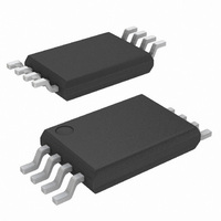
IC AMP HI SIDE CURR SENSE 8TSSOP
Manufacturer
STMicroelectronics
Datasheet
1.TSC1031IDT.pdf
(23 pages)
Specifications of TSC1031IPT
Amplifier Type
Current Sense
Number Of Circuits
1
Slew Rate
0.6 V/µs
-3db Bandwidth
700kHz
Current - Input Bias
10µA
Voltage - Input Offset
500µV
Current - Supply
200µA
Current - Output / Channel
26mA
Voltage - Supply, Single/dual (±)
2.7 V ~ 5.5 V, ±1.35 V ~ 2.75 V
Operating Temperature
-40°C ~ 125°C
Mounting Type
Surface Mount
Package / Case
8-TSSOP
Number Of Channels
Dual
Common Mode Rejection Ratio (min)
90 dB
Input Voltage Range (max)
5.5 V
Input Voltage Range (min)
2.7 V
Input Offset Voltage
1100 uV
Input Bias Current (max)
10 uA
Supply Current
300 uA
Maximum Operating Temperature
+ 125 C
Minimum Operating Temperature
- 40 C
Mounting Style
SMD/SMT
Operating Temperature Range
- 40 C to + 125 C
Supply Voltage (max)
5.5 V
Supply Voltage (min)
2.7 V
No. Of Amplifiers
1
Input Bias Current
15µA
Gain Db Max
100dB
Bandwidth
700kHz
Cmrr
105dB
Supply Voltage Range
2.7V To 5.5V
Rohs Compliant
Yes
Lead Free Status / RoHS Status
Lead free / RoHS Compliant
Output Type
-
Gain Bandwidth Product
-
Lead Free Status / Rohs Status
Lead free / RoHS Compliant
Other names
497-10453-2


Parameter definitions
4
4.1
4.2
4.3
10/23
Parameter definitions
Common mode rejection ratio (CMR)
The common mode rejection ratio (CMR) measures the ability of the current sensing
amplifier to reject any DC voltage applied on both inputs V
back to the input so that its effect can be compared with the applied differential signal. The
CMR is defined by the formula:
Supply voltage rejection ratio (SVR)
The supply voltage rejection ratio (SVR) measures the ability of the current-sensing
amplifier to reject any variation of the supply voltage V
input so that its effect can be compared with the applied differential signal. The SVR is
defined by the formula:
Gain (Av) and input offset voltage (V
The input offset voltage is defined as the intersection between the linear regression of the
V
V
calculated with the following formula.
out
sense
vs. V
= V
sense
sense1
curve with the X-axis (see
and V
V
os
out2
=
SVR
is the output voltage with V
V
CMR
sense1
Doc ID 16875 Rev 1
=
=
–
–
20
–
⎛
⎝
20
V
----------------------------------------------- -
⋅
sense1
V
⋅
log
out1
log
Figure
----------------------------- -
ΔV
------------------------------
ΔV
–
–
ΔV
CC
V
V
ΔV
icm
sense2
out2
out
⋅
4.). If V
out
⋅
Av
Av
sense
⋅
CC
os
out1
V
. The SVR is referred back to the
out1
)
p
= V
and V
is the output voltage with
⎞
⎠
sense2
m
. The CMR is referred
, then V
os
can be
TSC1031
Related parts for TSC1031IPT
Image
Part Number
Description
Manufacturer
Datasheet
Request
R

Part Number:
Description:
High-voltage high side current sense amplifier
Manufacturer:
STMicroelectronics
Datasheet:
Part Number:
Description:
High voltage, high side current sense amplifier
Manufacturer:
STMicroelectronics
Datasheet:
Part Number:
Description:
STMicroelectronics [RIPPLE-CARRY BINARY COUNTER/DIVIDERS]
Manufacturer:
STMicroelectronics
Datasheet:
Part Number:
Description:
STMicroelectronics [LIQUID-CRYSTAL DISPLAY DRIVERS]
Manufacturer:
STMicroelectronics
Datasheet:

Part Number:
Description:
BOARD EVAL FOR MEMS SENSORS
Manufacturer:
STMicroelectronics
Datasheet:
Part Number:
Description:
NPN TRANSISTOR POWER MODULE
Manufacturer:
STMicroelectronics
Datasheet:
Part Number:
Description:
TURBOSWITCH ULTRA-FAST HIGH VOLTAGE DIODE
Manufacturer:
STMicroelectronics
Datasheet:
Part Number:
Description:
Manufacturer:
STMicroelectronics
Datasheet:
Part Number:
Description:
DIODE / SCR MODULE
Manufacturer:
STMicroelectronics
Datasheet:
Part Number:
Description:
DIODE / SCR MODULE
Manufacturer:
STMicroelectronics
Datasheet:
Part Number:
Description:
Search -----> STE16N100
Manufacturer:
STMicroelectronics
Datasheet:
Part Number:
Description:
Search ---> STE53NA50
Manufacturer:
STMicroelectronics
Datasheet: