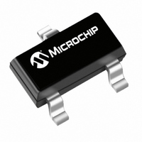
TC54VN2902ECB713 Microchip Technology, TC54VN2902ECB713 Datasheet - Page 6

TC54VN2902ECB713
Manufacturer Part Number
TC54VN2902ECB713
Description
IC VOLT DETECTOR 2.9V SOT23A
Manufacturer
Microchip Technology
Type
Simple Reset/Power-On Resetr
Specifications of TC54VN2902ECB713
Number Of Voltages Monitored
1
Output
Open Drain or Open Collector
Reset
Active Low
Voltage - Threshold
2.9V
Operating Temperature
-40°C ~ 85°C
Mounting Type
Surface Mount
Package / Case
SOT-23A-3
Threshold Voltage
2.9V
No. Of Supervisors / Monitors
1
Supply Voltage Range
0.7V To 6V, 0.7V To 10V
Reset Type
Active-Low
Supply Current
1.1µA
Delay Time
200µs
Monitored Voltage
1.1 V to 6 V
Manual Reset
Not Resettable
Watchdog
No Watchdog
Supply Voltage (max)
10 V
Supply Voltage (min)
0.7 V
Supply Current (typ)
3.6 uA
Maximum Power Dissipation
240 mW
Maximum Operating Temperature
+ 85 C
Mounting Style
SMD/SMT
Minimum Operating Temperature
- 40 C
Lead Free Status / RoHS Status
Lead free / RoHS Compliant
Reset Timeout
-
Lead Free Status / Rohs Status
Lead free / RoHS Compliant
Other names
158-2036-2
158-2036-2
TC54VN2902ECB71TR
158-2036-2
TC54VN2902ECB71TR
Available stocks
Company
Part Number
Manufacturer
Quantity
Price
Part Number:
TC54VN2902ECB713
Manufacturer:
MICROCHIP/微芯
Quantity:
20 000
TC54
4.0
4.1
Although the TC54 has a pre-programmed V
sometimes necessary to make adjustments during pro-
totyping. This can be accomplished by connecting an
external resistor divider to a TC54, which has a V
lower than that of V
To maintain detector accuracy, the bleeder current
through the divider should be significantly higher than
the 1 µA operating current required by the TC54. A
reasonable value for this bleeder current is 100 µA (100
times the 1 µA required by the TC54). For example, if
V
of R
can be rounded to the nearest standard value and
plugged into the equation of Figure 4-1 to calculate
values for R
recommended.
FIGURE 4-1:
using external resistor divider.
DS21434G-page 6
DET
1
Where:
Note:
+ R
– = 2V and the desired trip point is 2.5V, the value
R
R
V
V
SOURCE
(V
SOURCE
2
1
APPLICATIONS INFORMATION
Modifying The Trip Point, V
2
DET
is 25 k (2.5V/100 µA). The value of R
V
SOURCE
In this example, V
greater than (V
1
– ) = Threshold Voltage setting of TC54
V
and R
= Voltage to be monitored
IN
SOURCE
=
Modify trip-point of the TC54
2
V
. 1% tolerance resistors are
SS
------------------- -
R 1
TC54
R
(Figure 4-1).
+
DET
1
R 2
– )
=
SOURCE
V
DET
V
OUT
-
must be
DET
DET
1
– , it is
DET
–
+ R
–
2
4.2
Low operating power and small physical size make the
TC54 series ideal for many voltage detector applica-
tions, such as those shown in Figures 4-2, 4-3 and 4-4.
Figure 4-2 shows a low-voltage gate drive protection
circuit that prevents overheating of the logic-level
MOSFET due to insufficient gate voltage. When the
input signal is below the threshold of the TC54VN, its
output grounds the gate of the MOSFET. Figure 4-3 and
Figure 4-4 show the TC54 in conventional voltage
monitoring applications.
FIGURE 4-2:
Protection.
FIGURE 4-3:
FIGURE 4-4:
Pwr
Sply
+
–
+
– –
Other Applications
TC54VX
4.3V
V
TC54VX
V
TC54VX
V
IN
V
SS
SS
IN
270
V
V
IN
SS
MOSFET Low Drive
Battery Voltage Monitor.
Power Good Monitor.
2004 Microchip Technology Inc.
V
OUT
V
V
OUT
OUT
V
CC
MTP3055EL
R
Power Good
L
BATLOW


