MCP111-475E/TO Microchip Technology, MCP111-475E/TO Datasheet
MCP111-475E/TO
Specifications of MCP111-475E/TO


Related parts for MCP111-475E/TO


MCP111-475E/TO Summary of contents
Page 1
... The MCP111 and MCP112 are available in eight different trip voltages. The MCP111 has an open-drain output with an active- low pin (V ). This device will assert V OUT voltage on the V pin is below the trip-point voltage ...
Page 2
... HYS 0.023 — 0.139 0.026 — 0.158 0.029 — 0.174 0.029 — 0.176 0.031 — 0.185 0.044 — 0.263 0.046 — 0.278 = 100 k (only MCP111), PU Units Conditions uA, V < 0.2V RST RST µ +25°C (Note -40°C to +85°C A (Note +25°C (Note 1) ...
Page 3
... OD t RPU Sym Min Typ Max — 90 — t RPU t — 130 — RPD t — 5 — RT MCP111/112 = 1V to 5.5V 100 k (only MCP111), PU Units Conditions V I =500 µ TRIP(MIN mA, For only OH MCP112 (push-pull output) µA t RPD 5.5V 100 Units Conditions Figure 1-1 and µ ...
Page 4
... MCP111/112 TEMPERATURE CHARACTERISTICS Electrical Specifications: Unless otherwise noted, all limits are specified for V MCP111 -40°C to +125°C. A Parameters Temperature Ranges Specified Temperature Range Specified Temperature Range Maximum Junction Temperature Storage Temperature Range Package Thermal Resistances Thermal Resistance, 3L-SOT23 Thermal Resistance, 3L-SC-70 ...
Page 5
... FIGURE 2-5: 1.6 MCP112-475 1.4 5.5V 1.2 2.1V 1 2.8V 0.8 0.6 0.4 0.2 0 1.0 FIGURE 2-6: MCP111/112 = 100 k (only MCP111; PU +125°C +85°C -40°C +25°C 2.0 3.0 4.0 5.0 6 vs. V (MCP111-195 +125°C +85°C -40°C +25°C 2 ...
Page 6
... V = 4.4V 0.170 DD 0.040 0.160 0.150 0.030 0.140 0.020 0.130 0.120 0.010 0.110 0.100 0.000 140 0.00 vs. FIGURE 2-12 4.4V 100 k (only MCP111; PU +125°C +85°C -40°C +25°C 0.25 0.50 0.75 1.00 I (mA vs. I (MCP111-195 2.7V +125°C +85°C -40°C +25°C 0.25 ...
Page 7
... DD 600 = 1. 500 400 300 200 100 0.001 80 120 FIGURE 2-18: (25 °C). MCP111/112 = 100 k (only MCP111; PU MCP112-300 V = 3.1V DD -40 °C +25 °C +85 °C +125 °C 0.25 0.50 0.75 1.00 I (mA vs. I (MCP112-300 OH OH MCP112-300 V = 3.1V DD +25 °C -40 °C +85 °C +125 ° ...
Page 8
... TRIP(min) 100 110 -40 FIGURE 2-23: (MCP112-300). 250 MCP112-475 200 150 100 50 0 -40 85 110 FIGURE 2-24: (MCP112-475). = 100 k (only MCP111; PU MCP111-195 V increasing from 2.1V V increasing from increasing 0V - 2.8V DD from 4.0V V increasing DD from 5.5V - 110 Temperature (°C) t vs. Temperature ...
Page 9
... Microchip Technology Inc 5.5V 0.1500 MCP111-195 0.1400 0.1300 0.1200 V increasing DD from 4.0V 0.1100 0.1000 0.0900 0.0800 85 110 -40 FIGURE 2-27: (MCP112-475). increasing from: 85 110 MCP111/112 = 100 k (only MCP111; PU MCP112-475 V increasing from 5.0V V increasing from 4.9V V increasing from 5.5V V increasing from 4.8V - 110 Temperature (° ...
Page 10
... MCP111/112 3.0 PIN DESCRIPTION The descriptions of the pins are listed in Table 3-1. TABLE 3-1: PIN FUNCTION TABLE Pin No. Symbol SOT23-3 T0-92 SC- Output State OUT Ground reference Positive power supply DD DS21889A-page 10 Function Falling: > TRIP < TRIP Rising: > TRIP HYS < TRIP HYS 2004 Microchip Technology Inc. ...
Page 11
... 0 MCP11X Microcontroller µF RESET 1 V INPUT OUT (Active-Low Note 1: R may be required with the MCP111 PU due to the open-drain output. Resistor R is not required with the MCP112. PU FIGURE 4-1: Typical Application Circuit TRIPMAX V TRIPMIN 1V V OUT FIGURE 4-2: V Operation as Determined by the V OUT ...
Page 12
... DD duration decreases with increases in V Figure 4-3 shows a typical transient duration vs. reset comparator overdrive for which the MCP111/112 will not generate a reset pulse. It shows that the farther below the trip point the transient pulse goes, the dura- tion of the pulse required to cause a reset gets shorter. ...
Page 13
... MCP111T-290E/LB MHNN MCP111T-300E/LB MJNN MCP111T-315E/LB MKNN MCP111T-450E/LB MLNN MCP111T-475E/LB MMNN MCP111T-195I/TT MCP111T-240ETT MCP111T-270E/TT MCP111T-290E/TT MCP111T-300E/TT MCP111T-315E/TT MCP111T-450E/TT MCP111T-475E/TT Legend: 1 Part Number + temperature range and voltage (two-digit code) 2 Part Number + temperature range and voltage (two-digit code) 3 Lot ID number 4 Year and work week 5 ...
Page 14
... MCP111/112 3-Lead Plastic Small Outline Transistor (NB) (SOT-23 Dimension Limits Number of Pins Pitch Outside lead pitch (basic) Overall Height Molded Package Thickness Standoff § Overall Width Molded Package Width Overall Length Foot Length Foot Angle Lead Thickness Lead Width Mold Draft Angle Top ...
Page 15
... E1 .045 .053 D .071 .089 L .004 .016 c .003 .010 B .006 .016 a 8° 12° b 8° 12° MCP111/112 A2 A1 MILLIMETERS* MIN MAX 3 0.65 BSC. 1.30 BSC. 0.80 1.10 0.80 1.00 0.00 .010 1.80 2.40 1.15 1.35 1.80 2.25 0.10 0.41 ...
Page 16
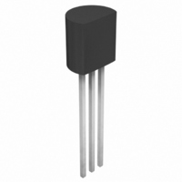
... MCP111/112 3-Lead Plastic Transistor Outline (TO) (TO-92 Dimension Limits Number of Pins Pitch Bottom to Package Flat Overall Width Overall Length Molded Package Radius Tip to Seating Plane Lead Thickness Lead Width Mold Draft Angle Top Mold Draft Angle Bottom *Controlling Parameter Notes: Dimensions D and E1 do not include mold flash or protrusions. Mold flash or protrusions shall not exceed .010” ...
Page 17
... Standard Reel Component Orientation 2004 Microchip Technology Inc Carrier Cavity Dimensions Dimensions 3.15 2.77 1. 2.4 2.4 1.19 User Direction of Feed P, Pitch Reverse Reel Component Orientation MCP111/112 W Output Reel Quantity Diameter in Units mm 3000 180 3000 180 Marking Device W, Width Pin 1 of Carrier Tape DS21889A-page 17 ...
Page 18
... MCP111/112 FIGURE 5-3: TO-92 DEVICES Device Marking 3 LEAD TO-92 Device Marking 2 LEAD TO-92 Standard Reel Component Orientation DS21889A-page 18 P, Pitch W, Width of Carrier Tape W, Width of Carrier Tape Reverse Reel Component Orientation 2004 Microchip Technology Inc ...
Page 19
... MCP111/112 . MCP111T-195I/NB: SOT-23B-3, Tape and Reel, 1.95V MicroPower Voltage Detector, open-drain, -40°C to +85°C. MCP111T-315E/LB: SC-70-3, Tape and Reel, 3.15V MicroPower Voltage Detector, open-drain, -40°C to +125°C. MCP111-300E/TO: TO-92-3, 3.00V MicroPower Voltage Detector, open-drain, -40°C to +85°C. MCP112T-290E/NB: SOT-23B-3, Tape and Reel, 2 ...
Page 20
... MCP111/112 NOTES: DS21889A-page 20 2004 Microchip Technology Inc. ...
Page 21
... PICLAB, PICtail, PowerCal, PowerInfo, PowerMate, PowerTool, rfLAB, rfPICDEM, Select Mode, Smart Serial, SmartTel and Total Endurance are trademarks of Microchip Technology Incorporated in the U.S.A. and other countries. SQTP is a service mark of Microchip Technology Incorporated in the U.S.A. All other trademarks mentioned herein are property of their respective companies. ...
Page 22
... Via Quasimodo, 12 20025 Legnano (MI) Milan, Italy Tel: 39-0331-742611 Fax: 39-0331-466781 Netherlands Waegenburghtplein 4 NL-5152 JR, Drunen, Netherlands Tel: 31-416-690399 Fax: 31-416-690340 United Kingdom 505 Eskdale Road Winnersh Triangle Wokingham Berkshire, England RG41 5TU Tel: 44-118-921-5869 Fax: 44-118-921-5820 05/28/04 2004 Microchip Technology Inc. ...