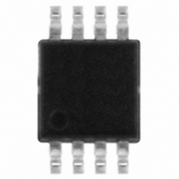
STM6904PWEDS6F STMicroelectronics, STM6904PWEDS6F Datasheet

STM6904PWEDS6F
Specifications of STM6904PWEDS6F
Available stocks
Related parts for STM6904PWEDS6F
STM6904PWEDS6F Summary of contents
Page 1
... STM6904TWEDS6F 3.078 STM6904TGEDS6F 3.078 STM6904SYEDS6F 2.955 STM6904SFEDS6F 2.955 STM6904PWEDS6F 2.866 1. Other reset threshold voltages and t ST sales office for availability. January 2008 This is preliminary information on a new product now in development or undergoing evaluation. Details are subject to change without notice. Quad, ultralow voltage supervisor ≥ ...
Page 2
Contents 1 Description . . . . . . . . . . . . . . . . . . . . . . . . . . . . . . . . . . . . . ...
Page 3
List of tables Table 1. Device summary . . . . . . . . . . . . . . . . . . . . . . . . . . . . . . . . . ...
Page 4
List of figures Figure 1. Logic diagram . . . . . . . . . . . . . . . . . . . . . . . . . . . . . . . . . ...
Page 5
Description The STM6904 supervisor is a low voltage/low supply current processor supervisor, designed to monitor up to four system power supply voltages. This device is targeted at applications such as Set-Top Boxes (STBs), portable, battery-powered systems, networking and communication ...
Page 6
Table 2. Signal names and functions Pin Name V2IN V3IN 6 V4IN 7 TR SEL 8 RST 6/21 Type Input Active-low manual reset input with internal pull-up resistor Primary supply ...
Page 7
Pin descriptions 2.1 Push-button reset input (MR) When MR goes low the RST output is driven low, RST remains low as long low and for t after MR returns to high. The active-low input has an ...
Page 8
TR input SEL Allows user to select between two values of t tied to V (210 ms Figure 3. Functional block diagram V CC V2IN V3IN V4IN SEL 1. Internal pull-up ...
Page 9
Figure 4. Typical hardware hookup application diagram (600mV) TRIP (600mV) TRIP R4 V CC3 must be tied ...
Page 10
Operation The STM6904 provides the ability to monitor critical voltages such as power-supply and battery voltage levels, while interfacing easily to the system controllers/microprocessors. Figure 4 shows typical hardware hookup for monitoring four voltages; two fixed thresholds (customer-selectable, factory-programmed ...
Page 11
Voltage monitoring Figure 5. MR timing waveforms t MLMH MR t MLMR RST Figure 6. Voltage monitoring diagram V VXIN RST1/2 V RSTIN RST t REC , t RD ai13974 t rec ai13975 11/21 ...
Page 12
... These are stress ratings only and operation of the device at these or any other conditions above those indicated in the Operating sections of this specification is not implied. Exposure to absolute maximum rating conditions for extended periods may affect device reliability. Refer also to the STMicroelectronics SURE Program and other relevant quality documents. Table 3. ...
Page 13
DC and AC parameters This section summarizes the operating measurement conditions and the DC and AC characteristics of the device. Designers should check that the operating conditions in their circuit match the operating conditions when relying on the quoted ...
Page 14
Table 4. DC and AC characteristics (continued) Alter- Sym Description native ( V2IN reset threshold RST2 TH2 Reset threshold V HYST hysteresis RST delay RD CC (5) t REC t RST time-out period RP Adjustable ...
Page 15
Table 4. DC and AC characteristics (continued) Alter- Sym Description native MR glitch immunity MR pull-up resistance 1. Valid for ambient operating temperature 10k ohm (typ) internal pull-up resistor. 3. The leakage current measured on the RST pin ...
Page 16
Package mechanical data In order to meet environmental requirements, ST offers these devices in ECOPACK packages. These packages have a lead-free second level interconnect. The category of second level interconnect is marked on the package and on the inner ...
Page 17
Table 5. TSSOP 8-lead package mechanical data mm Symbol Min Typ A A1 0.00 A2 0.75 0.85 b 0.22 c 0.08 ccc D 2.80 3.00 e 0.65 E 4.65 4.90 E1 2.80 3.00 L 0.40 0.60 L1 0.95 L2 0.25 ...
Page 18
Part numbering Table 6. Ordering information scheme Example: Device type STM6904 Reset threshold voltages Suffix V V RST1 TZ 3.078 2.333 TW 3.078 1.683 TG 3.078 1.110 SY 2.955 2.188 SF 2.955 1.050 PW 2.866 1.683 (1) t REC ...
Page 19
... Package marking information Table 7. Marking description Part marking V RST1 STM6904TZEDS6F 3.078 STM6904TWEDS6F 3.078 STM6904TGEDS6F 3.078 STM6904SFEDS6F 2.955 STM6904SYEDS6F 2.955 STM6904PWEDS6F 2.866 (V) V (V) RST2 2.333 MSOP (TSSOP8) 1.683 MSOP (TSSOP8) 1.110 MSOP (TSSOP8) 1.050 MSOP (TSSOP8) 2.188 MSOP (TSSOP8) 1.683 MSOP (TSSOP8) ...
Page 20
Revision history Table 8. Document revision history Date Revision 19-Dec-2007 28-Jan-2008 20/21 1 Initial release. 2 Updated cover page, Figure 6 Changes and Table 4. ...
Page 21
... Information in this document is provided solely in connection with ST products. STMicroelectronics NV and its subsidiaries (“ST”) reserve the right to make changes, corrections, modifications or improvements, to this document, and the products and services described herein at any time, without notice. All ST products are sold pursuant to ST’s terms and conditions of sale. ...


