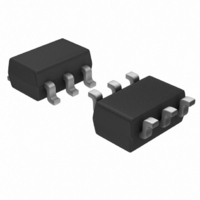
STM6710LWB6F STMicroelectronics, STM6710LWB6F Datasheet

STM6710LWB6F
Specifications of STM6710LWB6F
Available stocks
Related parts for STM6710LWB6F
STM6710LWB6F Summary of contents
Page 1
... Small 6-pin SOT23 package ■ ROHS compliant Table 1. Device summary V1IN Part number (V) STM6710DWB6F 5 STM6710FWB6F Adj STM6710KWB6F Adj STM6710LWB6F Adj December 2009 Low-voltage, high-accuracy, triple/quad voltage Applications ■ Telecommunications ■ Set-top boxes ■ Networking equipment ■ Server/workstations ■ Desktop and notebook computers ■ ...
Page 2
Contents Contents 1 Description . . . . . . . . . . . . . . . . . . . . . . . . . . . . . . . . . . . . ...
Page 3
STM6700, STM6710 List of tables Table 1. Device summary . . . . . . . . . . . . . . . . . . . . . . . . . . . . . . . ...
Page 4
List of figures List of figures Figure 1. Logic diagram . . . . . . . . . . . . . . . . . . . . . . . . . . . . . . ...
Page 5
STM6700, STM6710 1 Description The STM6710 is a precision voltage-monitoring supervisor with the capability to monitor triple/quad voltages and combines competitive reset threshold accuracy with low-power consumption. Factory-trimmed reset threshold options for monitoring 5.0 V, 3.3 V, 2.5 V and ...
Page 6
Description Figure 1. Logic diagram 1. Open drain Table 2. Signal names Pin Name 1 V1IN V2IN V3IN 4 V4IN 5 GND 6 RESET Figure 2. Pinout SOT23-6 1. Open drain Note: For the STM6700 and ...
Page 7
STM6700, STM6710 1.1 Pin descriptions V1IN, V3IN,V4IN (VxIN) The VxIN pins are used for nominal input voltages for 1.8 V, 2.5 V and 5.0 V supplies. The voltage at this pin is compared against an internal factory-programmed voltage trip point, ...
Page 8
Description Figure 3. Functional block diagram V1IN (1) V2IN V CC V3IN V4IN 0.62V REF 1. The STM6700 and STM6710Q are powered via the V2IN input which is the supply voltage. When this pin the input is ...
Page 9
STM6700, STM6710 2 Operation The STM6710 is capable of monitoring voltages in a multi-supply application. The device is available in several pre-set voltage thresholds for power supplies of 1.8 V, 2.5 V, 3.0 V, 3.3 V and ...
Page 10
Operation Figure 6. RESET output diagram 10/22 VxIN V THx RESET 10 Doc ID 16887 Rev 1 STM6700, STM6710 V THx 90 AM04622v1 ...
Page 11
STM6700, STM6710 2.2 Adjustable thresholds (input configurations) The STM6700/STM6710 may be configured to monitor several options with adjustable reset thresholds. The threshold voltages at each adjustable input VxIN is typically 0.62 V. Thus to monitor a voltage > 0.62 V, ...
Page 12
Operation 2.3 Unused inputs Connect unused monitor inputs to a supply voltage greater in magnitude than their specified threshold voltages. For unused VxIN adjustable inputs connect ohm resistor between unused input and V2IN or (V (device power ...
Page 13
... These are stress ratings only and operation of the device at these or any other conditions above those indicated in the operating sections of this specification is not implied. Exposure to absolute maximum rating conditions for extended periods may affect device reliability. Refer also to the STMicroelectronics SURE Program and other relevant quality documents. Table 3. ...
Page 14
DC and AC parameters 4 DC and AC parameters This section summarizes the DC and AC characteristics of the device. The parameters in the DC and AC characteristics table that follows are derived from tests performed under the test conditions. ...
Page 15
STM6700, STM6710 Table 4. DC and AC characteristics (continued) Alt. Symbol Parameter Reset V to reset RPD asserted delay Reset timeout REC delay t Propagation delay PD V RESET output low OL RESET ...
Page 16
Package mechanical data 5 Package mechanical data In order to meet environmental requirements, ST offers these devices in different grades of ® ECOPACK packages, depending on their level of environmental compliance. ECOPACK specifications, grade definitions and product status are available ...
Page 17
STM6700, STM6710 Figure 9. SOT23-6L – 6-lead small outline transistor package mechanical drawing Table 5. SOT23-6L – 6-lead small outline transistor package mechanical data Sym θ mm Min Typ Max ...
Page 18
Package mechanical data Figure 10. SOT23-6L landing pattern Figure 11. Carrier tape for SOT23-6L T TOP COVER TAPE K 0 Table 6. Carrier tape dimensions for SOT23-6L Package 8.00 1.50 1.75 SOT23-6 +0.30/ +0.10/ ±0.10 –0.10 –0.00 ...
Page 19
STM6700, STM6710 6 Part numbering Table 7. Ordering information scheme Example: Device type (1) STM6700 STM6710 Threshold combination Refer to Table 8: STM6700/STM6710 device selector summary Package WB = SOT23-6 Temperature range 6 = –40 °C to +85 °C Shipping ...
Page 20
... STM6710DWB6F 5 3.3 STM6710EWB6F Adj 3.3 STM6710FWB6F Adj 3.3 STM6710GWB6F 5 3.3 STM6710HWB6F 5 3.3 STM6710IWB6F Adj 3.3 STM6710JWB6F Adj 3.3 STM6710KWB6F Adj 3.3 STM6710LWB6F Adj 3.3 STM6710MWB6F Adj 3 STM6710NWB6F Adj 3 STM6710OWB6F Adj 3 STM6710PWB6F Adj 3 STM6710QWB6F Adj V CC STM6700WB6F Adj V CC 20/22 Table 8 ...
Page 21
STM6700, STM6710 8 Revision history Table 9. Document revision history Date 09-Dec-2009 Revision 1 Initial release. Doc ID 16887 Rev 1 Revision history Changes 21/22 ...
Page 22
... Information in this document is provided solely in connection with ST products. STMicroelectronics NV and its subsidiaries (“ST”) reserve the right to make changes, corrections, modifications or improvements, to this document, and the products and services described herein at any time, without notice. All ST products are sold pursuant to ST’s terms and conditions of sale. ...


