ADM6713SAKSZ-REEL7 Analog Devices Inc, ADM6713SAKSZ-REEL7 Datasheet
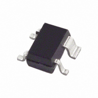
IC SUPERVISOR MPU 2.93V SC70-4

ADM6713SAKSZ-REEL7

Manufacturer Part Number
ADM6713SAKSZ-REEL7
Description
IC SUPERVISOR MPU 2.93V SC70-4
Manufacturer
Analog Devices Inc
Type
Simple Reset/Power-On Resetr
Datasheet

Specifications of ADM6713SAKSZ-REEL7

Number Of Voltages Monitored
1
Output
Open Drain or Open Collector
Reset
Active Low
Reset Timeout
140 ms Minimum
Voltage - Threshold
2.93V
Operating Temperature
-40°C ~ 125°C
Mounting Type
Surface Mount
Package / Case
SC-70-4, SC-82-4, SOT-323-4, SOT-343
Threshold Voltage
2.93V
No. Of Supervisors / Monitors
1
Supply Voltage Range
1.2V To 5.5V
Reset Type
Active-Low / Open-Drain
Supply Current
20mA
Delay Time
240ms
Number Of Elements
1
Monitored Voltage 1 (typ)
2.5/3/3.3/5V
Threshold Voltage 1 (max)
2.96V
Battery Backup Switching
No
Watchdog Timer
No
Chip Enable Signals
No
Reset Active Time
640ms
Manual Reset
Yes
Package Type
SC-70
Operating Supply Voltage (min)
1V
Operating Supply Voltage (max)
5.5V
Reset Threshold Voltage (max)
2.96V
Reset Threshold Voltage (min)
2.89V
Family Name
ADM6713
Operating Temp Range
-40C to 125C
Operating Temperature Classification
Automotive
Power Fail Detection
No
Mounting
Surface Mount
Pin Count
3 +Tab
Lead Free Status / RoHS Status
Lead free / RoHS Compliant
Lead Free Status / RoHS Status
Lead free / RoHS Compliant, Lead free / RoHS Compliant
Other names
ADM6713SAKSZ-REEL7
ADM6713SAKSZ-REEL7TR

Available stocks

Company
Part Number
Manufacturer
Quantity
Price
Part Number:
ADM6713SAKSZ-REEL7
Manufacturer:
AD
Quantity:
3 000
Part Number:
ADM6713SAKSZ-REEL7
Manufacturer:
ADI/亚德诺
Quantity:
20 000
Company:
Part Number:
ADM6713SAKSZ-REEL7
Quantity:
1 959
FEATURES
Specified over temperature
Low power consumption (12 μA)
Precision monitoring of 2.5 V, 3 V, 3.3 V,
Reset timeout period of 140 ms (minimum)
Manual reset input
Output stages
Reset assertion down to 1 V V
Power supply glitch immunity
4-lead SC70 package
APPLICATIONS
Microprocessor systems
Computers
Controllers
Intelligent instruments
Automotive systems
GENERAL DESCRIPTION
The ADM6711/ADM6713 are reset generator circuits suitable
for use in microprocessor-based systems. They provide a reset
signal on power-up, power-down, and whenever the supply
voltage falls below a preset threshold. In addition, both parts
have a debounced manual reset input so that a reset signal can
also be initiated with an external switch or logic signal.
With six different reset threshold options available ranging
from 2.32 V to 4.63 V, the ADM6711/ADM6713 are suitable for
monitoring 2.5 V, 3 V, 3.3 V, and 5 V supplies. A reset timeout
of at least 140 ms occurs when V
This gives the supply voltage time to stabilize before the
microprocessor starts up.
The ADM6711 has a push-pull output, so no additional
external components are needed. The ADM6713 open-drain
output requires an external pull-up resistor that can be
connected to a voltage higher than V
Rev. A
Information furnished by Analog Devices is believed to be accurate and reliable. However, no
responsibility is assumed by Analog Devices for its use, nor for any infringements of patents or other
rights of third parties that may result from its use. Specifications subject to change without notice. No
license is granted by implication or otherwise under any patent or patent rights of Analog Devices.
Trademarks and registered trademarks are the property of their respective owners.
and 5 V power supply voltages
Push-pull RESET output (ADM6711)
Open-drain RESET output (ADM6713)
CC
CC
rises above the threshold.
CC
, if desired.
One Technology Way, P.O. Box 9106, Norwood, MA 02062-9106, U.S.A.
Tel: 781.329.4700
Fax: 781.461.3113
The parts are highly reliable with accurate voltage references
and immunity to fast, negative-going transients on V
current consumption and space-efficient, 4-lead SC70
packaging make the ADM6711/ADM6713 ideal for use in low
power portable applications.
Microprocessor Supervisory
V
V
MR
MR
CC
CC
V
V
FUNCTIONAL BLOCK DIAGRAMS
MR
REF
REF
ADM6711
ADM6713
ADM6711/
ADM6713
Circuit in 4-Lead SC70
GND
V
Figure 3. Typical Operating Circuit
CC
DEBOUNCE
DEBOUNCE
RESET
ADM6711/ADM6713
©2006 Analog Devices, Inc. All rights reserved.
*ADM6713 ONLY
GENERATOR
GENERATOR
Figure 1.
Figure 2.
*R
PULL-UP
RESET
RESET
240ms
240ms
MICROPROCESSOR
RESET
SYSTEM
GND
V
CC
www.analog.com
CC
RESET
RESET
GND
GND
. Low

Related parts for ADM6713SAKSZ-REEL7

ADM6713SAKSZ-REEL7 Summary of contents

Page 1

FEATURES Specified over temperature Low power consumption (12 μA) Precision monitoring of 2 3.3 V, and 5 V power supply voltages Reset timeout period of 140 ms (minimum) Manual reset input Output stages Push-pull RESET output (ADM6711) ...

Page 2

ADM6711/ADM6713 TABLE OF CONTENTS Features .............................................................................................. 1 Applications....................................................................................... 1 Functional Block Diagrams............................................................. 1 General Description ......................................................................... 1 Revision History ............................................................................... 2 Specifications..................................................................................... 3 Absolute Maximum Ratings............................................................ 5 ESD Caution.................................................................................. 5 Pin Configuration and Function Descriptions............................. 6 REVISION HISTORY 12/06—Rev. 0 ...

Page 3

SPECIFICATIONS V = full operating range MIN unless otherwise noted. Table 1. Parameter Min SUPPLY V Operating Voltage Range 1.0 CC 1.2 Supply Current RESET VOLTAGE THRESHOLD ADM671_L 4.56 4.50 4.44 ADM671_M 4.31 ...

Page 4

ADM6711/ADM6713 Parameter RESET OPEN-DRAIN OUTPUT LEAKAGE CURRENT MANUAL RESET (MR) Input Threshold Pull-Up Resistance Minimum Pulse width Glitch Immunity Reset Delay Min Typ Max 100 200 Rev Page ...

Page 5

ABSOLUTE MAXIMUM RATINGS T = 25°C, unless otherwise noted. A Table 2. Parameter V CC RESET (Push-Pull) RESET (Open-Drain) MR Input Current Output Current RESET Rate of Rise θ Thermal Impedance, SC70 JA Operating ...

Page 6

ADM6711/ADM6713 PIN CONFIGURATION AND FUNCTION DESCRIPTIONS Table 4. Pin Function Descriptions Pin No. Mnemonic Description 1 GND Ground Reference for All Signals (0 V). 2 RESET Active Low Logic Input. RESET remains low while V 240 ms (typical) after V ...

Page 7

TYPICAL PERFORMANCE CHARACTERISTICS 5. –40 – TEMPERATURE (°C) ...

Page 8

ADM6711/ADM6713 CIRCUIT DESCRIPTION The ADM6711/ADM6713 are designed to protect the integrity of a system’s operation by ensuring the proper operation of the system during power-up, power-down, and brownout conditions. When the ADM6711/ADM6713 are powered up, the RESET output remains low ...

Page 9

OUTLINE DIMENSIONS ORDERING GUIDE RESET Model Threshold (V) ADM6711LAKS-REEL 4.63 1 ADM6711LAKSZ-REEL 4.63 ADM6711LAKS-REEL-7 4.63 1 ADM6711LAKSZ-REEL-7 4.63 ADM6711MAKS-REEL 4.38 ADM6711MAKS-REEL-7 4.38 1 ADM6711MAKSZ-REEL-7 4.38 ADM6711TAKS-REEL 3.08 1 ADM6711TAKSZ-REEL 3.08 ADM6711TAKS-REEL-7 3.08 1 ADM6711TAKSZ-REEL-7 3.08 ADM6711SAKS-REEL 2.93 1 ADM6711SAKSZ-REEL 2.93 ...

Page 10

... ADM6711/ADM6713 RESET Threshold (V) Model ADM6713TAKS-REEL-7 3.08 ADM6713TAKSZ-REEL-7 1 3.08 ADM6713SAKS-REEL 2.93 1 ADM6713SAKSZ-REEL 2.93 ADM6713SAKS-REEL-7 2.93 1 ADM6713SAKSZ-REEL-7 2.93 ADM6713RAKS-REEL 2.63 1 ADM6713RAKSZ-REEL 2.63 ADM6713RAKS-REEL-7 2.63 1 ADM6713RAKSZ-REEL-7 2.63 ADM6713ZAKS-REEL 2.32 1 ADM6713ZAKSZ-REEL 2.32 ADM6713ZAKS-REEL-7 2.32 1 ADM6713ZAKSZ-REEL-7 2. Pb-free part. Temperature Package Range Description −40°C to +125°C 4-Lead SC70 − ...

Page 11

NOTES Rev Page ADM6711/ADM6713 ...

Page 12

ADM6711/ADM6713 NOTES ©2006 Analog Devices, Inc. All rights reserved. Trademarks and registered trademarks are the property of their respective owners. C03754-0-12/06(A) Rev Page ...

Related keywords