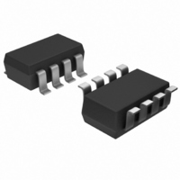
MAX6751KA29+T Maxim Integrated Products, MAX6751KA29+T Datasheet - Page 5

MAX6751KA29+T
Manufacturer Part Number
MAX6751KA29+T
Description
IC MPU/RESET CIRC SOT23-8
Manufacturer
Maxim Integrated Products
Type
Multi-Voltage Supervisorr
Datasheet
1.MAX6749KAT.pdf
(14 pages)
Specifications of MAX6751KA29+T
Number Of Voltages Monitored
2
Output
Open Drain or Open Collector
Reset
Active Low
Reset Timeout
Adjustable/Selectable
Voltage - Threshold
2.925V, Adj
Operating Temperature
-40°C ~ 125°C
Mounting Type
Surface Mount
Package / Case
SOT-23-8
Monitored Voltage
1.575 V to 5 V
Undervoltage Threshold
2.867 V, Adjustable
Overvoltage Threshold
2.984 V, Adjustable
Output Type
Active Low, Open Drain
Manual Reset
Not Resettable
Watchdog
Watchdog
Battery Backup Switching
No Backup
Supply Voltage (max)
5.5 V
Supply Voltage (min)
1 V
Supply Current (typ)
5 uA
Maximum Power Dissipation
714 mW
Maximum Operating Temperature
+ 125 C
Mounting Style
SMD/SMT
Minimum Operating Temperature
- 40 C
Power Fail Detection
No
Power-up Reset Delay (typ)
9.487 ms
Lead Free Status / RoHS Status
Lead free / RoHS Compliant
Other names
MAX6751KA29+TTR
(V
CC
MAX6746
MAX6747
27.0
26.6
26.2
25.8
25.4
25.0
= +5V, T
—
—
1
2
3
4
-50
V
µP Reset Circuits with Capacitor-Adjustable
CC
vs. TEMPERATURE (V
-25
FALLING AT 1mV/μs
A
= +25°C, unless otherwise noted.)
V
CC
0
MAX6748–
MAX6751
TEMPERATURE (°C)
TO RESET DELAY
_______________________________________________________________________________________
PIN
25
—
—
1
2
3
4
50
CC
75
FALLING)
MAX6752
MAX6753
100
—
—
1
2
3
4
125
Reset/Watchdog Timeout Delay
RESET IN
0.60
0.56
0.52
0.48
0.44
0.40
Typical Operating Characteristics (continued)
NAME
SET0
GND
SWT
SRT
MR
1.5
TIMEOUT PERIOD vs. SUPPLY VOLTAGE
C
SWT
2.0
= C
2.5 3.0 3.5
RESET AND WATCHDOG
SRT
Manual Reset Input. Pull MR low to manually reset the device. Reset
remains asserted for the reset timeout period after MR is released.
Reset Input. High-impedance input to the adjustable reset comparator.
Connect RESET IN to the center point of an external resistor-divider to
set the threshold of the externally monitored voltage.
Logic Input. SET0 selects watchdog window ratio or disables the
watchdog timer. See Table 1.
Watchdog Timeout Input.
MAX6746–MAX6751: Connect a capacitor between SWT and ground to
set the basic watchdog timeout period (t
the formula t
Farads. Extend the basic watchdog timeout period by using the WDS
input. Connect SWT to ground to disable the watchdog timer function.
MAX6752/MAX6753: Connect a capacitor between SWT and ground to
set the slow watchdog timeout period (t
watchdog period by the formula: t
seconds and C
by pinstrapping SET0 and SET1 (Connect SET0 high and SET1 low to
disable the watchdog timer function.) See Table 1.
Reset Timeout Input. Connect a capacitor from SRT to GND to select
the reset timeout period. Determine the period as follows: t
10
Ground
= 100pF
6
x C
V
SRT
CC
(V)
4.0 4.5
with t
WD
SWT
= 5.06 x 10
RP
5.0
in seconds and C
in Farads. The fast watchdog timeout period is set
5.5
6.0
6
x C
FUNCTION
SWT
9.0
8.5
8.0
7.5
7.0
6.5
6.0
WD2
1.5
with t
SRT
C
= 0.65 x 10
SWT
WD2
RESET AND WATCHING TIMEOUT
2.0
WD
PERIOD vs. SUPPLY VOLTAGE
in Farads.
= C
WD
2.5
). Determine the period by
). Determine the slow
SRT
Pin Description
in seconds and C
= 1500pF
3.0
9
3.5
x C
V
CC
(V)
SWT
4.0
WATCHDOG
4.5
RP
with t
RESET
= 5.06 x
5.0
SWT
WD2
5.5
in
in
6.0
5


