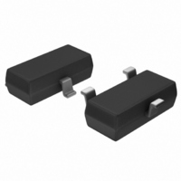
DS1813R-10+T&R Maxim Integrated Products, DS1813R-10+T&R Datasheet - Page 5

DS1813R-10+T&R
Manufacturer Part Number
DS1813R-10+T&R
Description
IC ECONORST 5V W/PB 10% SOT-23-3
Manufacturer
Maxim Integrated Products
Series
EconoResetr
Type
Simple Reset/Power-On Resetr
Datasheet
1.DS1813R-5TR.pdf
(5 pages)
Specifications of DS1813R-10+T&R
Number Of Voltages Monitored
1
Output
Open Drain or Open Collector
Reset
Active Low
Reset Timeout
100 ms Minimum
Voltage - Threshold
4.35V
Operating Temperature
-40°C ~ 85°C
Mounting Type
Surface Mount
Package / Case
SOT-23-3, TO-236-3, Micro3™, SSD3, SST3
Monitored Voltage
0 V to 5.5 V
Undervoltage Threshold
4.25 V
Overvoltage Threshold
4.49 V
Output Type
Active Low, Open Drain
Manual Reset
Resettable
Watchdog
No Watchdog
Battery Backup Switching
No Backup
Power-up Reset Delay (typ)
300 ms
Supply Voltage (max)
5.5 V
Supply Voltage (min)
0 V
Supply Current (typ)
40 uA
Maximum Operating Temperature
+ 85 C
Mounting Style
SMD/SMT
Minimum Operating Temperature
- 40 C
Power Fail Detection
Yes
Lead Free Status / RoHS Status
Lead free / RoHS Compliant
Other names
DS1813R-10+T&R
DS1813R-10+T&RTR
DS1813R-10+T&RTR
NOTES:
1) All voltages are referenced to ground.
2) Measured with V
3) A 1kΩ external resistor may be required in some applications for proper operation of the
4) Measured with RST output open.
5) t
6) V
7) This value is for reference in defining values for t
PART MARKING CODES
Maxim/Dallas Semiconductor cannot assume responsibility for use of any circuitry other than circuitry entirely embodied in a Maxim/Dallas Semiconductor product.
No circuit patent licenses are implied. Maxim/Dallas Semiconductor reserves the right to change the circuitry and specifications without notice at any time.
M a x i m I n t e g r a t e d P r o d u c t s , 1 2 0 S a n G a b r i e l D r i v e , S u n n y v a l e , C A 9 4 0 8 6 4 0 8 - 7 3 7 - 7 6 0 0
The Maxim logo is a registered trademark of Maxim Integrated Products, Inc. The Dallas logo is a registered trademark of Dallas Semiconductor Corporation.
microprocessor reset control circuit.
proper operation or use of the device.
R
OH
“A,” “B,” and “C” represent the device type.
= 5µs.
and I
810 . . . . DS1810
811 . . . . DS1811
812 . . . . DS1812
813 . . . . DS1813
815 . . . . DS1815
816 . . . . DS1816
817 . . . . DS1817
818 . . . . DS1818
OH
are a function of the value of R
CC
≥ 2.7V.
© 2006 Maxim Integrated Products • Printed USA
P
and the associated output load conditions.
5 of 5
RPD
“D” represents the device tolerance.
and should not be considered a requirement for
A . . . . . . 5%
B . . . . . . 10%
C . . . . . . 15%
D . . . . . . 20%
DS1813


