LM3700XBBP-270 National Semiconductor, LM3700XBBP-270 Datasheet - Page 6
LM3700XBBP-270
Manufacturer Part Number
LM3700XBBP-270
Description
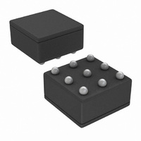
IC MPU SUPERVISOR 2.7V 9MICROSMD
Manufacturer
National Semiconductor
Type
Simple Reset/Power-On Resetr
Datasheet
1.LM3700XBBP-270.pdf
(13 pages)
Specifications of LM3700XBBP-270
Number Of Voltages Monitored
1
Output
Push-Pull, Totem Pole
Reset
Active Low
Reset Timeout
20 ms Minimum
Voltage - Threshold
2.7V
Operating Temperature
-40°C ~ 85°C
Mounting Type
Surface Mount
Package / Case
9-MicroSMD
Lead Free Status / RoHS Status
Lead free / RoHS Compliant
Other names
LM3700XBBP-270TR


www.national.com
LLO
LLO OUTPUT
LM3700/LM3701 Series Electrical Characteristics
Symbol
Limits in the standard typeface are for T
specified: V
Note 1: Absolute Maximum Ratings indicate limits beyond which damage to the device may occur. Operating Ratings indicate conditions for which the device
is intended to be functional, but do not guarantee specific performance limits. For guaranteed specifications and test conditions, see the Electrical Characteristics.
The guaranteed specifications apply only for the test conditions listed. Some performance characteristics may degrade when the device is not operated under the
listed conditions.
Note 2: The Human Body model is a 100 pF capacitor discharged through a 1.5 kΩ resistor into each pin. The machine model is a 200pF capacitor discharged
directly into each pin.
Note 3: The maximum allowable power dissipation is a function of the maximum junction temperature, T
and the ambient temperature, T
Where the value of θ
V
V
V
LLOTH
V
t
LLOT
CD
OH
OL
CC
LLO Output
Voltage
LLO Output
Threshold
(V
falling)
Low-Line
Comparator
Hysteresis
Low-Line
Comparator Delay
LLO
= +2.2V to 5.5V.
Parameter
J-A
− V
for the micro SMD package is 220˚C/W.
RST
A
, V
. The maximum allowable power dissipation at any ambient temperture is calculated using:
CC
V
V
V
V
V
V
V
CC
CC
CC
CC
CC
CC
CC
falling at 1mV/µs
>
>
>
>
>
>
J
2.25V, I
2.7V, I
4.5V, I
2.25V, I
2.7V, I
4.5V, I
= 25˚C and limits in boldface type apply over full operating range. Unless otherwise
SINK
SINK
SOURCE
SOURCE
Conditions
SINK
SOURCE
= 1.2mA
= 3.2mA
= 900µA
= 500µA
= 800µA
= 300µA
6
V
1.01 • V
CC
0.8 V
0.8 V
J
Min
(MAX), the junction-to-ambient thermal resistance, θ
(Continued)
− 1.5V
CC
CC
RST
0.0032 • V
1.02 • V
Typ
20
RST
RST
1.03 • V
Max
0.3
0.3
0.4
RST
Units
mV
µs
J-A
V
V
,
Related parts for LM3700XBBP-270
Image
Part Number
Description
Manufacturer
Datasheet
Request
R

Part Number:
Description:
Microprocessor Supervisory Circuit with Low Line Output
Manufacturer:
National Semiconductor
Datasheet:
Part Number:
Description:
LM3700/LM3701 Microprocessor Supervisory Circuit with Low Line Output; Package: MICRO SMD; No of Pins: 9; Qty per Container: 3000; Container: Reel
Manufacturer:
National Semiconductor
Part Number:
Description:
National Semiconductor [8-Bit D/A Converter]
Manufacturer:
National Semiconductor
Datasheet:
Part Number:
Description:
National Semiconductor [Media Coprocessor]
Manufacturer:
National Semiconductor
Datasheet:
Part Number:
Description:
Digitally Controlled Tone and Volume Circuit with Stereo Audio Power Amplifier, Microphone Preamp Stage and National 3D Sound
Manufacturer:
National Semiconductor
Datasheet:
Part Number:
Description:
Digitally Controlled Tone and Volume Circuit with Stereo Audio Power Amplifier, Microphone Preamp Stage and National 3D Sound
Manufacturer:
National Semiconductor
Datasheet:
Part Number:
Description:
AC97 Rev 2 Codec with Sample Rate Conversion and National 3D Sound
Manufacturer:
National Semiconductor
Part Number:
Description:
Manufacturer:
National Semiconductor
Datasheet:
Part Number:
Description:
Manufacturer:
National Semiconductor
Datasheet:
Part Number:
Description:
General Purpose, Low Voltage, Low Power, Rail-to-Rail Output Operational Amplifiers
Manufacturer:
National Semiconductor
Datasheet:
Part Number:
Description:
8-bit 20 MSPS flash A/D converter.
Manufacturer:
National Semiconductor
Datasheet:
Part Number:
Description:
Low Noise Quad Operational Amplifier
Manufacturer:
National Semiconductor
Datasheet:
Part Number:
Description:
Quad Differential Line Receivers
Manufacturer:
National Semiconductor
Datasheet:
Part Number:
Description:
Quad High Speed Trapezoidal? Bus Transceiver
Manufacturer:
National Semiconductor
Datasheet: