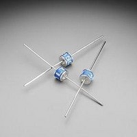
LT800C Littelfuse Inc, LT800C Datasheet - Page 2

LT800C
Manufacturer Part Number
LT800C
Description
GAS TRIGGER TUBE 800V CORE
Manufacturer
Littelfuse Inc
Series
LTr
Datasheet
1.LT350C.pdf
(2 pages)
Specifications of LT800C
Spark Over Voltage
800V
Impulse Discharge Current
400A
Package / Case
Non-Standard SMD
Mounting Type
Surface Mount
Lead Free Status / RoHS Status
Lead free / RoHS Compliant
Tolerance
-
Lead Free Status / RoHS Status
Lead free / RoHS Compliant, Lead free / RoHS Compliant
Gas Plasma Voltage Dependent Switches
Switching Gas Discharge Tubes
Device Ratings and Specifications
RoHS
Electrical Life:
Maximum Ratings:
Notes:
(1) Measured on recommended test circuit (fig 1.)
(2) Measured @ 100 Volts DC
(3) Current required for transition to on-state
(4) Measured @ 1 MHz, zero Volt bias
(5) Measured on recommended test circuit (fig 2.)
Definitions:
V BO – Breakover Voltage
V S – Switching Voltage
V T @ 5A – Nominal Off-state Voltage at 5A
I DRM – Off-state Current
I BO – Nominal Breakover Current
C o - Max Capacitance
V BO to V T – Max switching time from V BO to V T
LT230
LT800
Number
Switching Cycles (5) ………………………………………………………… 400,000
Peak Discharge Current (5) ………………………………………………………. 400 A
Max Switching Frequency ………………………………………………………. 100 Hz
Storage Temperature T STG ……………………………………………………… -40 - +150˚C
Operating Temperature
Part
V
Fig 1. Recommended breakover voltage test circuit
(Discharge current = 10-20mA, sensitivity of
Peak Voltage Detect = 10-30mA)
O.C. DC voltage =1000
LT Series
195 –265
680 – 920
V BO (1)
(V)
0.22µF
51KΩ
……………………………………………………… -40 - +150˚C
184 – 276
640 - 960
(V)
V S
P.V.D.
V T
LT device
(V)
15
15
@ 5A
w w w . l i t t e l f u s e . c o m
I DRM (2)
(A)
1.0
1.0
I BO (3)
50
50
(mA)
V
1000Vdc
C O (4)
2.0
2.0
(pF)
Fig 2. Recommended Life Circuit
V BO to V T
20K
330nF
(nS)
25
25
Ω
0.4µH
LT device
317
7


