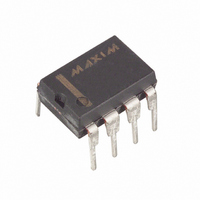
DS1834D+ Maxim Integrated Products, DS1834D+ Datasheet - Page 3

DS1834D+
Manufacturer Part Number
DS1834D+
Description
IC ECONORST DUAL ACT HI PP 8-DIP
Manufacturer
Maxim Integrated Products
Series
EconoResetr
Type
Multi-Voltage Supervisorr
Datasheet
1.DS1834AUTR.pdf
(7 pages)
Specifications of DS1834D+
Number Of Voltages Monitored
2
Output
Push-Pull, Totem Pole
Reset
Active High
Reset Timeout
200 ms Minimum
Voltage - Threshold
3.3V, 5V
Operating Temperature
-40°C ~ 85°C
Mounting Type
Through Hole
Package / Case
8-DIP (0.300", 7.62mm)
Monitored Voltage
3.3 V, 5 V
Undervoltage Threshold
4.5 V, 2.8 V
Overvoltage Threshold
2.97 V, 4.75 V
Output Type
Active High
Manual Reset
Resettable
Watchdog
No Watchdog
Battery Backup Switching
No Backup
Power-up Reset Delay (typ)
500 ms
Supply Voltage (max)
5.5 V
Supply Voltage (min)
1.2 V
Supply Current (typ)
50 uA
Maximum Operating Temperature
+ 85 C
Mounting Style
Through Hole
Minimum Operating Temperature
- 40 C
Power Fail Detection
Yes
Lead Free Status / RoHS Status
Lead free / RoHS Compliant
DS1834/A/D
Tolerance Select
The DS1834 provides two TOL inputs for individual customization of the DS1834 to specific application
requirements. If the TOL for the 5-volt supply is tied to the 5-volt input a 10% tolerance is selected for
the 5 volt supply. If the TOL for the 3.3-volt supply is tied to the 3.3-volt input, a 20% tolerance is
selected for the 3.3-volt supply. If TOL inputs are tied to ground, the 5-volt input will be set at a 5%
tolerance and the 3.3-volt input would be set to a 10% tolerance.
Pushbutton Reset
The DS1834 provides a pushbutton switch for manual reset control. When at least one of the DS1834
resets are not in a reset cycle, a pushbutton reset can be generated by pulling the
pin low for at
PBRST
least 2 ms. When the pushbutton is held low, both resets are forced active and will remain active for about
350 ms after the pushbutton is released. The pushbutton input is pulled high through an internal
40 k =pull-up resistor and debounced via internal circuitry. See Figure 3 for an application example and
Figure 4 for the timing diagram.
PUSHBUTTON RESET Figure 3
TIMING DIAGRAM: PUSHBUTTON RESET Figure 4
3 of 7


