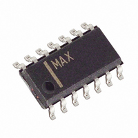
MAX8215CSD+ Maxim Integrated Products, MAX8215CSD+ Datasheet - Page 6

MAX8215CSD+
Manufacturer Part Number
MAX8215CSD+
Description
IC MONITOR VOLT MPU 14-SOIC
Manufacturer
Maxim Integrated Products
Type
Multi-Voltage Supervisorr
Datasheet
1.MAX8216CSD.pdf
(12 pages)
Specifications of MAX8215CSD+
Number Of Voltages Monitored
5
Output
Open Drain or Open Collector
Reset Timeout
20 µs Typical Propagation Delay
Voltage - Threshold
±5V, ±12V, Adj
Operating Temperature
0°C ~ 70°C
Mounting Type
Surface Mount
Package / Case
14-SOIC (3.9mm Width), 14-SOL
Monitored Voltage
- 12 V or - 5 V or 5 V or 12 V
Undervoltage Threshold
4.521 V or 10.431 V or - 10.431 V or - 4.348 V
Overvoltage Threshold
4 V or 10.749 V or - 10.749 V or - 4.482 V
Manual Reset
No
Watchdog
No
Battery Backup Switching
No
Power-up Reset Delay (typ)
85 ms to 300 ms
Supply Voltage (max)
11 V
Supply Voltage (min)
2.7 V
Supply Current (typ)
250 uA
Maximum Power Dissipation
667 mW
Mounting Style
SMD/SMT
Maximum Operating Temperature
+ 70 C
Chip Enable Signals
No
Minimum Operating Temperature
0 C
Output Type
Open Drain
Power Fail Detection
No
Lead Free Status / RoHS Status
Lead free / RoHS Compliant
Reset
-
Lead Free Status / Rohs Status
Lead free / RoHS Compliant
The MAX8215/MAX8216 contain 5 comparators (Figure
1). The comparator with its output labeled DOUT is dis-
tinguished from the others in that it can be set up to mon-
itor various voltages; each of the other 4 comparators
monitors a specific voltage. The DOUT comparator’s
noninverting input is available external to the device; its
inverting input is tied internally to the reference.
The MAX8215/MAX8216 comparators have open-drain
outputs. Thus, these devices require pull-up resistors
for proper operation. See the Typical Operating Circuit.
Open-drain outputs are useful for driving LEDs and for
situations in which the comparator outputs must be
connected together (i.e., wire-ORed).
Bypass V
±5V, ±12V (±15V) Dedicated
Microprocessor Voltage Monitors
_____________________Pin Description
6
_______________Detailed Description
10, 11,
12, 13
PIN
14
_______________________________________________________________________________________
1
2
3
4
5
6
7
8
9
DD
(+15V)
NAME
PGND
OUT4,
OUT3,
OUT2,
(-15V)
DOUT
OUT1
VREF
+12V
GND
-12V
+5V
V
DIN
with 0.1µF connected to PGND.
-5V
DD
Output of the internal 1.24V reference
Ground. Connect to PGND.
Input for monitoring +5V supply
Input for monitoring -5V supply
MAX8215 input for monitoring +12V
(MAX8216 input for monitoring +15V)
MAX8215 input for monitoring -12V
(MAX8216 input for monitoring -15V)
Noninverting input of the auxiliary
comparator. Its inverting input is tied
to the internal reference.
Power-supply ground. Bypass V
to this pin.
Output of the auxiliary comparator
Outputs of the four dedicated com-
parators
Power-supply positive voltage input.
Bypass to PGND.
FUNCTION
DD
When the voltage on a typical comparator’s input is
at or near the voltage on the other input, ambient
noise generally causes the comparator output to
oscillate. The most common way to eliminate this
problem is by using hysteresis. When the two com-
parator input voltages are equal, hysteresis causes
one comparator input voltage to move quickly past
the other, thus taking the input out of the region
where oscillation occurs. Standard comparators
need external resistors for hysteresis; these resistors
are not necessary when using any of the MAX8215
and MAX8216 comparators because hysteresis is
built in.
Figure 1. Block Diagram
__________Applications Information
( ) ARE FOR
MAX8216 ONLY.
+12V (+15V)
-12V (-15V)
+5V
-5V
DIN
1.24V REFERENCE
MAX8215
MAX8216
Hysteresis
OUT1
OUT2
OUT3
VREF
V
PGND
GND
OUT4
DOUT
DD


