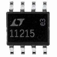
LT1121CS8-5#PBF Linear Technology, LT1121CS8-5#PBF Datasheet - Page 18

LT1121CS8-5#PBF
Manufacturer Part Number
LT1121CS8-5#PBF
Description
IC REG LDO 5V 150MA 8-SOIC
Manufacturer
Linear Technology
Specifications of LT1121CS8-5#PBF
Regulator Topology
Positive Fixed
Voltage - Output
5V
Voltage - Input
Up to 30V
Voltage - Dropout (typical)
0.42V @ 150mA
Number Of Regulators
1
Current - Output
150mA
Operating Temperature
0°C ~ 125°C
Mounting Type
Surface Mount
Package / Case
8-SOIC (3.9mm Width)
Primary Input Voltage
30V
Output Voltage Fixed
5V
Dropout Voltage Vdo
420mV
No. Of Pins
8
Output Current
150mA
Operating Temperature Range
0°C To +125°C
Msl
MSL 1 - Unlimited
Rohs Compliant
Yes
Lead Free Status / RoHS Status
Lead free / RoHS Compliant
Current - Limit (min)
-
Available stocks
Company
Part Number
Manufacturer
Quantity
Price
APPLICATIO S I FOR ATIO
LTC1608
The dynamic performance is excellent for input frequen-
cies up to and beyond the Nyquist limit of 250kHz.
Effective Number of Bits
The effective number of bits (ENOBs) is a measurement of
the resolution of an ADC and is directly related to the
S/(N + D) by the equation:
where ENOB is the effective number of bits of resolution
and S/(N + D) is expressed in dB. At the maximum
sampling rate of 500kHz, the LTC1608 maintains above 14
bits up to the Nyquist input frequency of 250kHz (refer to
Figure 20).
18
ENOB = [S/(N + D) – 1.76]/6.02
Figure 19a. This FFT of the LTC1608’s Conversion of a
Full-Scale 3kHz Sine Wave Shows Outstanding Response
with a Very Low Noise Floor When Sampling at 500ksps
Figure 19b. Even with Inputs at 100kHz, the
LTC1608’s Dynamic Linearity Remains Robust
–120
–140
–100
–100
–120
–140
–20
–40
–60
–80
–20
–40
–60
–80
0
0
0
0
50
50
U
FREQUENCY (kHz)
FREQUENCY (kHz)
100
100
U
150
150
f
f
SINAD = 86.7dB
THD = –92.6dB
f
f
SINAD = 88.9dB
THD = –98dB
SAMPLE
IN
SAMPLE
IN
= 98.754kHz
= 2.807kHz
W
200
200
= 500kHz
= 500kHz
1608 F19b
1608 F19a
250
250
U
Total Harmonic Distortion
Total harmonic distortion (THD) is the ratio of the RMS
sum of all harmonics of the input signal to the fundamental
itself. The out-of-band harmonics alias into the frequency
band between DC and half the sampling frequency. THD is
expressed as:
where V1 is the RMS amplitude of the fundamental fre-
quency and V2 through Vn are the amplitudes of the
second through nth harmonics. THD vs Input Frequency is
shown in Figure 21. The LTC1608 has good distortion
performance up to the Nyquist frequency and beyond.
Intermodulation Distortion
If the ADC input signal consists of more than one spectral
component, the ADC transfer function nonlinearity can
produce intermodulation distortion (IMD) in addition to
THD. IMD is the change in one sinusoidal input caused by
the presence of another sinusoidal input at a different
frequency.
If two pure sine waves of frequencies fa and fb are applied
to the ADC input, nonlinearities in the ADC transfer
function can create distortion products at the sum and
difference frequencies of mfa nfb, where m and n = 0,
1, 2, 3, etc. For example, the 2nd order IMD terms include
THD
Figure 20. Effective Bits and Signal/(Noise + Distortion)
vs Input Frequency
20
16
15
14
13
12
11
10
9
8
1k
Log
V
2
10k
2
FREQUENCY (Hz)
V
3
2
V
100k
1
V
4
2
1608 F20
...
Vn
1M
98
92
86
80
74
68
62
56
50
2


