SG137AT Microsemi Analog Mixed Signal Group, SG137AT Datasheet - Page 2
SG137AT
Manufacturer Part Number
SG137AT
Description
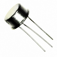
IC VOLTAGE REG NEG ADJ TO-39
Manufacturer
Microsemi Analog Mixed Signal Group
Datasheet
1.SG137T.pdf
(6 pages)
Specifications of SG137AT
Regulator Topology
Negative Adjustable
Voltage - Output
-1.2 ~ -37 V
Voltage - Input
Down to -36V
Number Of Regulators
1
Current - Output
100mA
Current - Limit (min)
500mA
Operating Temperature
-55°C ~ 150°C
Mounting Type
Through Hole
Package / Case
TO-39
Lead Free Status / RoHS Status
Lead free by exemption / RoHS compliant by exemption
Voltage - Dropout (typical)
-
Available stocks
Company
Part Number
Manufacturer
Quantity
Price

Company:
Part Number:
SG137AT/883
Manufacturer:
HITTITE
Quantity:
1 400
Company:
Part Number:
SG137AT/883B
Manufacturer:
MICROSEMI
Quantity:
1 400


2/92 Rev 1.1 2/94
Copyright
K Package:
R Package:
T Package:
IG Package:
L Package:
THERMAL DATA
ABSOLUTE MAXIMUM RATINGS
Power Dissipation ..........................................
Input to Output Voltage Differential ....................................
Storage Temperature Range ............................
Note 1. Exceeding these ratings could cause damage to the device.
RECOMMENDED OPERATING CONDITIONS
Input Voltage Range .............................. -(V
Note 2. Range over which the device is functional.
Note 3. These ratings are applicable for junction temperatures of less than 135°C.
ELECTRICAL CHARACTERISTICS
(Unless otherwise specified, these specifications apply over full operating ambient temperatures for SG137A/SG137 with -55°C T
SG237 with -25°C T
= 100mA (T and L packages). Although power dissipation is internally limited, these specifications are applicable for power dissipations of 2 for the T and
L packages, and 20 for the K, R, and IG packages. I
testing techniques are used which maintains junction and case temperatures equal to the ambient temperature.)
Reference Voltage
Line Regulation
Load Regulation
Thermal Regulation
Ripple Rejection
Adjust Pin Current
Adjust Pin Current Change
Thermal Resistance-
Thermal Resistance-
Thermal Resistance-
Thermal Resistance-
Thermal Resistance-
Thermal Resistance-
Thermal Resistance-
Thermal Resistance-
Thermal Resistance-
Thermal Resistance-
(Note 6)
1994
Parameter
(Note 4, 6)
(Note 4)
A
(Note 6)
150°C, SG337A/SG337 with 0°C T
(Note 5)
Junction to Ambient
Junction to Ambient
Junction to Ambient
Junction to Ambient
Junction to Ambient
Junction to Leads
Junction to Leads
Junction to Leads
Junction to Leads
Junction to Leads
I
3V
3V
10mA
T
V
T
3V
10mA
OUT
T
|V
|V
|V
|V
C
C
A
A
OUT
A
ADJ
ADJ
= 25°C, 10ms pulse
= 25°C
,
,
,
,
,
OUT
OUT
OUT
OUT
= 10mA, T
= 25°C
= -10V, f =120Hz
(Note 1)
,
,
,
,
,
|V
|V
|V
JC
JC
JC
JC
JC
| 5V, T
|
| 5V
|
= 0, T
= 10 F
JA
JA
JA
JA
JA
IN
IN
IN
................ 3.0°C/W
................ 5.0°C/W
................. 15°C/W
................ 3.5°C/W
................. 35°C/W
I
I
OUT
OUT
OUT
- V
............... 35°C/W
.............. 40°C/W
............ 120°C/W
.............. 42°C/W
............ 120°C/W
- V
- V
5V, T
5V
Internally Limited
MAX
A
OUT
OUT
OUT
-65 C to 150 C
+ 3.5V) to -36V
= 25°C
Test Conditions
A
is 1.5A for the K, R, and IG packages and 0.5A for the T and L packages. Low duty cycle pulse
I
I
A
|
|
|
A
MAX
MAX
= 25°C
= 25°C
= 25°C
(Note 2 & 3)
A
40V, 10mA
40V
40V, I
125°C, |V
40V
OUT
IN
2
I
- V
MAX
I
Operating Junction Temperature
Note A. Junction Temperature Calculation: T
Note B. The above numbers for
Operating Junction Temperature Range
OUT
OUT
Hermetic (K, R, T, L, IG-Packages) ...........................
Lead Temperature (Soldering, 10 Seconds) .............
SG137A/SG137 ............................................
SG237A/SG237 ............................................
SG337A/SG337 .............................................
| = 5.0V, and for I
I
MAX
thermal resistance of the package in a standard mount-
ing configuration. The
guidelines for the thermal performance of the device/pc-
board system. All of the above assume no ambient
airflow.
-1.238
-1.220
SG137A/SG237A
Min. Typ. Max.
60
70
OUT
SG137A/SG137 SERIES
-1.250
-1.250
= 500mA (K, R, and IG power packages) and I
0.005
0.002
0.1
0.2
1.0
0.2
10
66
80
65
5
-1.262
-1.280
11861 Western Avenue
0.01
0.02
100
0.5
1.0
25
50
5
2
JC
JA
are maximums for the limiting
-1.225
-1.200
Min. Typ. Max.
numbers are meant to be
66
L
SG137/SG237
INFINITY Microelectronics Inc.
(714) 898-8121
J
-1.250
-1.250
0.002
= T
0.01
0.3
0.3
0.5
15
20
60
77
65
2
A
+ (P
A
Garden Grove, CA 92841
-1.275
-1.300
-55°C to 150°C
-25°C to 150°C
150°C, SG237A/
0.02
0.02
100
D
0.5
1.0
25
50
0°C to 125°C
5
5
x
FAX: (714) 893-2570
JA
).
Units
%/W
%/V
150 C
300 C
mV
mV
dB
dB
%
%
V
V
A
A
A
OUT
Related parts for SG137AT
Image
Part Number
Description
Manufacturer
Datasheet
Request
R

Part Number:
Description:
IC USB LINE TERM EMI/ESD SC70-6
Manufacturer:
Microsemi Analog Mixed Signal Group
Datasheet:

Part Number:
Description:
IC USB LINE TERM EMI/ESD SC70-6
Manufacturer:
Microsemi Analog Mixed Signal Group
Datasheet:

Part Number:
Description:
IC TERM SCSI 9LINE MODE 24TSSOP
Manufacturer:
Microsemi Analog Mixed Signal Group
Datasheet:

Part Number:
Description:
IC TERM SCSI 9LINE MODE 28TSSOP
Manufacturer:
Microsemi Analog Mixed Signal Group
Datasheet:

Part Number:
Description:
IC TERM SCSI 9LINE LVD 24TSSOP
Manufacturer:
Microsemi Analog Mixed Signal Group
Datasheet:
Part Number:
Description:
IC TERM SCSI 9LINE MODE 36QSOP
Manufacturer:
Microsemi Analog Mixed Signal Group
Datasheet:

Part Number:
Description:
IC USB LINE TERM EMI/ESD SOT23-6
Manufacturer:
Microsemi Analog Mixed Signal Group
Datasheet:

Part Number:
Description:
IC USB LINE TERM EMI/ESD SOT23-6
Manufacturer:
Microsemi Analog Mixed Signal Group
Datasheet:

Part Number:
Description:
IC USB EMI FLTR ESD PROT SOT23-6
Manufacturer:
Microsemi Analog Mixed Signal Group
Part Number:
Description:
IC USB LINE TERM EMI/ESD SOT23-6
Manufacturer:
Microsemi Analog Mixed Signal Group
Datasheet:
Part Number:
Description:
IC AMP AUDIO PWR 10W STER 44SSOP
Manufacturer:
Microsemi Analog Mixed Signal Group
Datasheet:

Part Number:
Description:
IC CHARGER BATT USB LI-ION 20MLP
Manufacturer:
Microsemi Analog Mixed Signal Group
Datasheet:

Part Number:
Description:
IC LED DRIVER LINEAR 6-MLP
Manufacturer:
Microsemi Analog Mixed Signal Group
Datasheet:

Part Number:
Description:
IC LED DRIVR WT/CLR BCKLGT 8-MLP
Manufacturer:
Microsemi Analog Mixed Signal Group
Datasheet:

Part Number:
Description:
IC LED DRVR WT/CLR BCKLGT 8-MSOP
Manufacturer:
Microsemi Analog Mixed Signal Group
Datasheet: