L7905CP STMicroelectronics, L7905CP Datasheet - Page 7
L7905CP
Manufacturer Part Number
L7905CP
Description
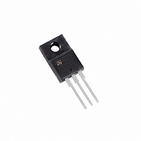
IC REG NEG 1.5A 5V TO-220FP
Manufacturer
STMicroelectronics
Specifications of L7905CP
Regulator Topology
Negative Fixed
Voltage - Output
-5V
Voltage - Input
Down to -35V
Voltage - Dropout (typical)
1.4V @ 1A
Number Of Regulators
1
Current - Output
1.5A
Operating Temperature
0°C ~ 125°C
Mounting Type
Through Hole
Package / Case
TO-220-3 Full Pack (Straight Leads)
Polarity
Negative
Number Of Outputs
1
Output Type
Fixed
Output Voltage
- 5 V
Output Current
0.5 A
Line Regulation
100 mV
Load Regulation
100 mV
Dropout Voltage (max)
1.4 V
Input Voltage Max
- 35 V
Maximum Operating Temperature
+ 150 C
Minimum Operating Temperature
0 C
Mounting Style
Through Hole
Primary Input Voltage
-10V
Output Voltage Fixed
-5V
Dropout Voltage Vdo
1.4V
No. Of Pins
3
Voltage Regulator Case Style
TO-220
Operating Temperature Range
0°C To +150°C
Rohs Compliant
Yes
Lead Free Status / RoHS Status
Lead free / RoHS Compliant
Current - Limit (min)
-
Lead Free Status / Rohs Status
Lead free / RoHS Compliant
Other names
497-7293-5
L7905CP
L7905CP
Available stocks
Company
Part Number
Manufacturer
Quantity
Price
Company:

Part Number:
L7905CP
Manufacturer:
AVAGO
Quantity:
2 561


Table 11: Electrical Characteristics Of L7924C (refer to the test circuits, T
I
(*) Load and line regulation are specified at constant junction temperature. Changes in V
separately. Pulse testing with low duty cycle is used.
APPLICATIONS INFORMATION
Figure 4: Fixed Output Regulator
NOTE:
1. To specify an output voltage, substitute voltage value for "XX".
2. Required for stability. For value given, capacitor must be solid tantalum. If aluminium electrolytics are used, at least ten times value should
be selected. C1 is required if regulator is located an appreciable distance from power supply filter.
3. To improve transient response. If large capacitors are used, a high current diode from input to output (1N4001 or similar) should be intro-
duced to protect the device from momentary input short circuit.
O
Symbol
V
SVR
= 500 mA, C
V
V
V
V
eN
V
I
O
I
sc
O
O
d
I
O
O
d
/ T Output Voltage Drift
d
(*)
(*)
Output Voltage
Output Voltage
Line Regulation
Load Regulation
Quiescent Current
Quiescent Current Change
Output Noise Voltage
Supply Voltage Rejection
Dropout Voltage
Short Circuit Current
I
= 2.2 µF, C
Parameter
O
= 1 µF unless otherwise specified).
T
I
V
V
V
I
I
T
I
V
I
B = 10Hz to 100KHz
I
mV
O
O
O
O
O
O
J
J
V
I
I
I
I
= -5 mA to -1 A
= -27 to -38 V
= -27 to -38 V
= -30 to -36 V
= 5 mA to 1.5 A
= 250 to 750 mA
= 5 mA to 1 A
= -27 to -38 V
= 5 mA
= 1 A
I
= 25°C
= 25°C
= 10 V f = 120Hz
T
Test Conditions
J
= 25°C
P
O
15 W
T
T
T
T
T
J
J
J
J
J
V
= 25°C
= 25°C
= 25°C
= 25°C
= 25°C
O
= 100
O
due to heating effects must be taken into account
-22.8
Min.
-23
54
J
= 0 to 125°C, V
Typ.
400
-24
-24
1.1
1.1
60
-1
L7900 SERIES
Max.
-24.5
-25.2
480
240
480
240
0.5
3
1
I
= -33V,
mV/°C
Unit
mV
mV
mA
mA
dB
V
V
V
A
V
7/18
Related parts for L7905CP
Image
Part Number
Description
Manufacturer
Datasheet
Request
R

Part Number:
Description:
STMicroelectronics [RIPPLE-CARRY BINARY COUNTER/DIVIDERS]
Manufacturer:
STMicroelectronics
Datasheet:
Part Number:
Description:
STMicroelectronics [LIQUID-CRYSTAL DISPLAY DRIVERS]
Manufacturer:
STMicroelectronics
Datasheet:

Part Number:
Description:
BOARD EVAL FOR MEMS SENSORS
Manufacturer:
STMicroelectronics
Datasheet:
Part Number:
Description:
NPN TRANSISTOR POWER MODULE
Manufacturer:
STMicroelectronics
Datasheet:
Part Number:
Description:
TURBOSWITCH ULTRA-FAST HIGH VOLTAGE DIODE
Manufacturer:
STMicroelectronics
Datasheet:
Part Number:
Description:
Manufacturer:
STMicroelectronics
Datasheet:
Part Number:
Description:
DIODE / SCR MODULE
Manufacturer:
STMicroelectronics
Datasheet:
Part Number:
Description:
DIODE / SCR MODULE
Manufacturer:
STMicroelectronics
Datasheet:
Part Number:
Description:
Search -----> STE16N100
Manufacturer:
STMicroelectronics
Datasheet:
Part Number:
Description:
Search ---> STE53NA50
Manufacturer:
STMicroelectronics
Datasheet:
Part Number:
Description:
NPN Transistor Power Module
Manufacturer:
STMicroelectronics
Datasheet:
Part Number:
Description:
DIODE / SCR MODULE
Manufacturer:
STMicroelectronics
Datasheet: