LP3991TL-1.2/NOPB National Semiconductor, LP3991TL-1.2/NOPB Datasheet - Page 4
LP3991TL-1.2/NOPB
Manufacturer Part Number
LP3991TL-1.2/NOPB
Description
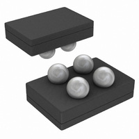
IC VREG 300MA 1.2V 4MICROSMD
Manufacturer
National Semiconductor
Series
PowerWise®r
Datasheet
1.LP3991TL-1.2EV.pdf
(12 pages)
Specifications of LP3991TL-1.2/NOPB
Regulator Topology
Positive Fixed
Voltage - Output
1.2V
Voltage - Input
1.65 ~ 4 V
Number Of Regulators
1
Current - Output
300mA (Min)
Operating Temperature
-40°C ~ 85°C
Mounting Type
Surface Mount
Package / Case
4-MicroSMD
Number Of Outputs
1
Polarity
Positive
Input Voltage Max
4 V
Output Voltage
1.2 V
Output Type
Fixed
Output Current
0.3 A
Voltage Regulation Accuracy
+/- 1 %
Maximum Operating Temperature
+ 85 C
Mounting Style
SMD/SMT
Minimum Operating Temperature
- 40 C
For Use With
LP3991TL-1.2EV - BOARD EVALUATION LP3991TL-1.2
Lead Free Status / RoHS Status
Lead free / RoHS Compliant
Voltage - Dropout (typical)
-
Current - Limit (min)
-
Lead Free Status / Rohs Status
Details
Other names
LP3991TL-1.2TR
Available stocks
Company
Part Number
Manufacturer
Quantity
Price
Company:

Part Number:
LP3991TL-1.2/NOPB
Manufacturer:
Texas Instruments
Quantity:
10 000


www.national.com
Enable Control Characteristics
I
(Note
V
V
Timing Characteristics
T
Transient
Response
I
EN
IR
ON
IL
IH
Electrical Characteristics con't.
Unless otherwise noted, V
Typical values and limits appearing in normal type apply for T
temperature range for operation, −40 to +125°C.
Note 1: Absolute Maximum Ratings are limits beyond which damage can occur. Operating Ratings are conditions under which operation of the device is
guaranteed. Operating Ratings do not imply guaranteed performance limits. For guaranteed performance limits and associated test conditions, see the Electrical
Characteristics tables.
Note 2: All Voltages are with respect to the potential at the GND pin.
Note 3: For further information on these packages please refer to the following application notes,AN-1112 Micro SMD Wafer Level Chip Scale Package.
Note 4: Internal thermal shutdown circuitry protects the device from permanent damage.
Note 5: The human body model is 100pF discharged through a 1.5kΩ resistor into each pin. The machine model is a 200pF capacitor discharged directly into
each pin.
Note 6: The maximum ambient temperature (T
dissipation of the device in the application (P
following equation: T
Note 7: Junction to ambient thermal resistance is dependant on the application and board layout. In applications where high maximum power dissipation is
possible, special care must be paid to thermal dissipation issues in board design.
Note 8: Full details can be found in JESD61-7
Note 9: All limits are guaranteed. All electrical characteristics having room-temperature limits are tested during production at T
Statistical Quality Control methods. Operation over the temperature specification is guaranteed by correlating the electrical characteristics to process and
temperature variations and applying statistical process control.
Note 10: V
Note 11: Dropout voltage is voltage difference between input and output at which the output voltage drops to 100mV below its nominal value. This parameter is
only specified for output voltages above 1.8V.
Note 12: The device maintains the regulated output voltage without a load.
Note 13: Short circuit current is measured with V
Note 14: This electrical specification is guaranteed by design.
Note 15: Enable Pin has an internal 1.2MΩ typical, resistor connected to GND.
Note 16: The device will operate with input voltages up to 4.0V. However special care should be taken in relation to thermal dissipation and the need to derate
the maximum allowable ambient temperature. See
Symbol
15)
IN(MIN)
Maximum Input Current at
V
Low Input Threshold
High Input Threshold
Turn On Time
Line Transient Response |δV
Load Transient Response |δV
Overshoot on Start-up
In-Rush Current
EN
= V
Input
A(max)
OUT(NOM)
= T
Parameter
+ 0.5V or 1.65V, whichever is greater. (See post DC/DC convertor example in application information section).
J(max-op)
EN
(Note
(Note
=950mV, V
- (θ
14)
JA
14)
× P
D(max)
A(max)
D(max)
OUT
), and the junction to ambient thermal resistance of the part / package in the application (θ
IN
OUT
(Note
OUT
) is dependant on the maximum operating junction temperature (T
).
= V
pulled to 0V.
| T
| T
OUT
6,
V
V
V
V
To 95% Level
V
δV
(Note
Note
rise
rise
EN
EN
IN
IN
IN(MIN)
(Note
IN
+ 0.5V, or 1.8V, whichever is higher. C
= 1.65V to 3.6V
= 1.65V to 3.6V
= 0V, V
= V
= T
= T
= 600mV
7)
14)
to 3.6V
IN
fall
fall
9)
= 3.6V
= 30µs
= 1µs
IN
A
= 25°C. Limits appearing in boldface type apply over the full junction
Conditions
= 3.6V
4
V
V
I
I
I
I
I
I
I
I
I
(Note
OUT
OUT
OUT
OUT
OUT
OUT
OUT
OUT
OUT
OUT
OUT
= 0 mA to 300mA
= 1mA to 300mA
= 300mA to 1mA
= 0mA to 200mA
= 1mA to 200mA
= 200mA to 1mA
= 0mA to 150mA
= 1mA to 150mA
= 150mA to 1mA
≤
> 2.0V
14)
2.0V
IN
0.001
Typ
100
140
140
110
110
100
600
= 1µF, I
80
80
60
70
50
3
6
0
J(max-op)
OUT
0.95
Min
= 125°C), the maximum power
J
= 1.0mA, C
= 25°C or correlated using
Limit
1000
Max
5.5
0.4
JA
2
OUT
), as given by the
=4.7µF.
(pk - pk)
Units
mV
mV
mA
µA
µs
%
V
V
Related parts for LP3991TL-1.2/NOPB
Image
Part Number
Description
Manufacturer
Datasheet
Request
R

Part Number:
Description:
IC VREG 300MA 2.8V 4MICROSMD
Manufacturer:
National Semiconductor
Datasheet:
Part Number:
Description:
IC VREG 300MA 1.55V 4USMD
Manufacturer:
National Semiconductor
Part Number:
Description:
IC VREG 300MA 1.5V 4MICROSMD
Manufacturer:
National Semiconductor
Datasheet:
Part Number:
Description:
IC REG 300MA 1.8V DGTL 4USMD
Manufacturer:
National Semiconductor
Datasheet:
Part Number:
Description:
IC VREG 300MA 3V DGTL 4USMD
Manufacturer:
National Semiconductor
Datasheet:
Part Number:
Description:
IC VREG 300MA 1.3V 4MICROSMD
Manufacturer:
National Semiconductor
Datasheet:
Part Number:
Description:
IC VREG 300MA 0.8V 4-USMD
Manufacturer:
National Semiconductor
Part Number:
Description:
IC VREG 300MA 2.5V 4-USMD
Manufacturer:
National Semiconductor
Part Number:
Description:
IC VREG 300MA 1.7V 4USMD
Manufacturer:
National Semiconductor
Part Number:
Description:
IC VREG 300MA 2.0V 4USMD
Manufacturer:
National Semiconductor

Part Number:
Description:
BOARD EVALUATION LP3991TL-1.2
Manufacturer:
National Semiconductor
Datasheet:
Part Number:
Description:
BOARD EVALUATION LP3991TL-1.3
Manufacturer:
National Semiconductor
Datasheet:
Part Number:
Description:
BOARD EVALUATION LP3991TL-1.5
Manufacturer:
National Semiconductor
Datasheet:
Part Number:
Description:
BOARD EVALUATION LP3991TL-1.8
Manufacturer:
National Semiconductor
Datasheet:

Part Number:
Description:
V REG, LDO, 300MA 1.2V, MICRO SMD-4
Manufacturer:
National Semiconductor
Datasheet: