NCP584HSN12T1G ON Semiconductor, NCP584HSN12T1G Datasheet - Page 12
NCP584HSN12T1G
Manufacturer Part Number
NCP584HSN12T1G
Description
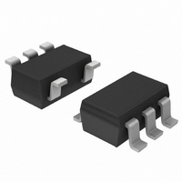
IC REG LDO 200MA 1.2V SOT23-5
Manufacturer
ON Semiconductor
Datasheet
1.NCP584HSN09T1G.pdf
(14 pages)
Specifications of NCP584HSN12T1G
Regulator Topology
Positive Fixed
Voltage - Output
1.2V
Voltage - Input
Up to 6V
Voltage - Dropout (typical)
0.3V @ 200mA
Number Of Regulators
1
Current - Output
200mA (Min)
Operating Temperature
-40°C ~ 85°C
Mounting Type
Surface Mount
Package / Case
SOT-23-5, SC-74A, SOT-25
Number Of Outputs
1
Polarity
Positive
Input Voltage Max
6 V
Output Voltage
1.2 V
Output Type
Fixed
Dropout Voltage (max)
0.5 V at 200 mA
Output Current
200 mA
Line Regulation
0.3 % / V
Load Regulation
40 mV
Voltage Regulation Accuracy
3 %
Maximum Power Dissipation
0.25 W
Maximum Operating Temperature
+ 85 C
Mounting Style
SMD/SMT
Minimum Operating Temperature
- 40 C
Lead Free Status / RoHS Status
Lead free / RoHS Compliant
Current - Limit (min)
-
Lead Free Status / Rohs Status
Lead free / RoHS Compliant
Other names
NCP584HSN12T1GOSTR
Available stocks
Company
Part Number
Manufacturer
Quantity
Price
Company:

Part Number:
NCP584HSN12T1G
Manufacturer:
ON Semiconductor
Quantity:
380
Part Number:
NCP584HSN12T1G
Manufacturer:
ON/安森美
Quantity:
20 000


Input Decoupling
to be connected between V
considerations, the traces of V
sufficiently wide in order to minimize noise and prevent
unstable operation.
Output Decoupling
capacitor on the V
tantalum capacitor with low Equivalent Series Resistance
(ESR). If you use a tantalum type capacitor with high ESR
A 1.0 mF tantalum capacitor is the recommended value
It is recommended to use a 2.2 mF or higher tantalum
450
400
350
300
250
200
150
100
50
0
0
Figure 32. Minimal ESR of Output Ceramic
20
40
Capacitor vs. Output Current
out
OUTPUT CURRENT (mA)
60
pin. For better performance, select a
C
out
C
out
80
= 2.2 mF
in
= 1 mF
and GND. For PCB layout
100 120 140 160 180 200
45
40
35
30
25
20
15
10
in
5
0
0
and GND should be
Figure 34. Minimal ESR of Output Ceramic
25
APPLICATION INFORMATION
V
T
out
V
FT Mode
A
Capacitor vs. Output Current
in
= 25°C
50
= 0.9 V
= 3 V
OUTPUT CURRENT (mA)
http://onsemi.com
C
out
75
C
out
= 2.2 mF
= 1 mF
12
100
value of this capacitor, output might be unstable. For a
ceramic type capacitor it is recommended connection
about 1 W resistor in series for the stability of output
voltage. The relation between Output Current of regulator
and ESR of an output capacitor is shown in Figures 32 to
34. Those charts show minimal value of ESR for stable
output voltage in Fast Transient mode. The minimal ESR
of an output ceramic capacitor in Low Power mode is
40 mW for all output voltages. For PCB layout
considerations, place the output capacitor close to the
output pin and keep the leads short as possible.
300
250
200
150
100
50
125
0
0
Figure 33. Minimal ESR of Output Ceramic
V
150
20
T
out
V
FT Mode
A
in
= 25°C
= 3.3 V
= 5 V
40
Capacitor vs. Output Current
175
OUTPUT CURRENT (mA)
60
200
C
out
C
80
out
= 2.2 mF
= 1 mF
100 120 140 160 180 200
V
T
out
V
FT Mode
A
in
= 25°C
= 1.2 V
= 3 V
Related parts for NCP584HSN12T1G
Image
Part Number
Description
Manufacturer
Datasheet
Request
R

Part Number:
Description:
Tri-Mode 200 mA CMOS LDO Regulator
Manufacturer:
ON Semiconductor
Datasheet:
Part Number:
Description:
ON Semiconductor [VOLTAGE REGULATOR]
Manufacturer:
ON Semiconductor
Datasheet:
Part Number:
Description:
357-036-542-201 CARDEDGE 36POS DL .156 BLK LOPRO
Manufacturer:
ON Semiconductor
Datasheet:
Part Number:
Description:
357-036-542-201 CARDEDGE 36POS DL .156 BLK LOPRO
Manufacturer:
ON Semiconductor
Datasheet:
Part Number:
Description:
357-036-542-201 CARDEDGE 36POS DL .156 BLK LOPRO
Manufacturer:
ON Semiconductor
Datasheet:
Part Number:
Description:
357-036-542-201 CARDEDGE 36POS DL .156 BLK LOPRO
Manufacturer:
ON Semiconductor
Datasheet:
Part Number:
Description:
357-036-542-201 CARDEDGE 36POS DL .156 BLK LOPRO
Manufacturer:
ON Semiconductor
Datasheet:
Part Number:
Description:
357-036-542-201 CARDEDGE 36POS DL .156 BLK LOPRO
Manufacturer:
ON Semiconductor
Datasheet:
Part Number:
Description:
357-036-542-201 CARDEDGE 36POS DL .156 BLK LOPRO
Manufacturer:
ON Semiconductor
Datasheet:
Part Number:
Description:
357-036-542-201 CARDEDGE 36POS DL .156 BLK LOPRO
Manufacturer:
ON Semiconductor
Datasheet:
Part Number:
Description:
357-036-542-201 CARDEDGE 36POS DL .156 BLK LOPRO
Manufacturer:
ON Semiconductor
Datasheet:
Part Number:
Description:
357-036-542-201 CARDEDGE 36POS DL .156 BLK LOPRO
Manufacturer:
ON Semiconductor
Datasheet:
Part Number:
Description:
Manufacturer:
ON Semiconductor
Datasheet:
Part Number:
Description:
Manufacturer:
ON Semiconductor
Datasheet: