NCP585LSN09T1G ON Semiconductor, NCP585LSN09T1G Datasheet
NCP585LSN09T1G
Specifications of NCP585LSN09T1G
Available stocks


Related parts for NCP585LSN09T1G


NCP585LSN09T1G Summary of contents
Page 1
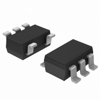
NCP585 Tri-Mode 300 mA CMOS LDO Regulator with Enable The NCP585 series of low dropout regulators are designed for portable battery powered applications which require precise output voltage accuracy, low quiescent current, and high ripple rejection. These devices feature an ...
Page 2
ref Current Limit CE Figure 1. Simplified Block Diagram for Active Low Figure 3. Simplified Block Diagram for Active High PIN FUNCTION DESCRIPTION HSON−6 SOT23−5 Pin Name ...
Page 3
MAXIMUM RATINGS Rating Input Voltage Input Voltage ( Pin) Input Voltage (ECO Pin) Output Voltage Output Current Power Dissipation ESD Capability, Human Body Model 100 pF 1.5 kW ESD Capability, Machine Model ...
Page 4
nominal +2.0 V 1.2 in out 1.0 0.8 0 nominal +0 out 0.4 V 0.2 out ECO = H 0.0 400 0 200 OUTPUT CURRENT, I out Figure 4. Output ...
Page 5
INPUT VOLTAGE Figure 10. Quiescent Current vs. Input Voltage 0.3 1.3 2.3 3.3 ...
Page 6
TEMPERATURE (°C) Figure 16. Output Voltage vs. Temperature 0.8 0.7 0.6 85°C 0.5 0.4 0.3 −40°C 0.2 0.1 0 100 150 OUTPUT CURRENT, I out Figure ...
Page 7
OUTPUT CURRENT, I out Figure 22. Dropout Voltage vs. Output Current 100 out ...
Page 8
Input Voltage 0.96 0.94 0.92 Output Voltage 0.90 ECO = Tantalum 1.0 mF out V = 0.9 V out 0. TIME, t (ms) 1.3 1.2 Load Current ...
Page 9
→ 1 1.0 0.1 ECO = H −1 1 Tantalum 1 −1 Tantalum 1.0 mF out I = 300 mA out −2.8 ...
Page 10
Unstable Region 10000 1000 100 Stable Region 10 1 0.1 No unstable region in LP Mode 0.01 100 0 50 150 OUTPUT CURRENT (mA) Figure 32. Output Stability, Output Capacitor ESR vs. Output Load Current (0.1 mF) 100000 Unstable ...
Page 11
... LP and FT Mode NCP585LSAN09T1G LP and FT Mode NCP585LSAN12T1G LP and FT Mode NCP585LSAN18T1G LP and FT Mode NCP585LSN09T1G LP and FT Mode NCP585LSN12T1G LP and FT Mode NCP585LSN18T1G LP and FT Mode †For information on tape and reel specifications, including part orientation and tape sizes, please refer to our Tape and Reel Packaging Specification Brochure, BRD8011/D. ...
Page 12
... 0. SOLDERING FOOTPRINT* 0.95 0.037 1.0 0.039 *For additional information on our Pb−Free strategy and soldering details, please download the ON Semiconductor Soldering and Mounting Techniques Reference Manual, SOLDERRM/D. SOT23−5 SN SUFFIX CASE 1212−01 ISSUE O NOTES 1.9 0.074 2.4 0.094 0.7 mm 0.028 ...
Page 13
... SCILLC is an Equal Opportunity/Affirmative Action Employer. This literature is subject to all applicable copyright laws and is not for resale in any manner. PUBLICATION ORDERING INFORMATION LITERATURE FULFILLMENT: Literature Distribution Center for ON Semiconductor P.O. Box 5163, Denver, Colorado 80217 USA Phone: 303−675−2175 or 800−344−3860 Toll Free USA/Canada Fax: 303− ...