LP3986TL-2929/NOPB National Semiconductor, LP3986TL-2929/NOPB Datasheet - Page 5
LP3986TL-2929/NOPB
Manufacturer Part Number
LP3986TL-2929/NOPB
Description
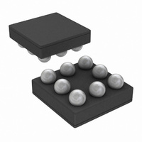
IC REG LDO DUAL 150MA 8MICROSMD
Manufacturer
National Semiconductor
Datasheet
1.LP3986TL-2518NOPB.pdf
(12 pages)
Specifications of LP3986TL-2929/NOPB
Regulator Topology
Positive Fixed
Voltage - Output
2.9V
Voltage - Input
2.7 ~ 6 V
Voltage - Dropout (typical)
0.06V @ 150mA
Number Of Regulators
2
Current - Output
150mA
Current - Limit (min)
300mA
Operating Temperature
-40°C ~ 125°C
Mounting Type
Surface Mount
Package / Case
8-MicroSMD
Lead Free Status / RoHS Status
Lead free / RoHS Compliant
Other names
LP3986TL-2929
LP3986TL-2929TR
LP3986TL-2929TR
Available stocks
Company
Part Number
Manufacturer
Quantity
Price
Company:

Part Number:
LP3986TL-2929/NOPB
Manufacturer:
Texas Instruments
Quantity:
10 000


ρn(1/f)
I
V
V
Xtalk
C
C
EN
IL
IH
IN
OUT
Note 1: Absolute Maximum Ratings are limits beyond which damage to the device may occur. Operating Ratings are conditions under which operation of the
device is guaranteed. Operating Ratings do not imply guaranteed performance limits. For guaranteed performance limits and associated test conditions, see the
Electrical Characteristics tables.
Note 2: All voltages are with respect to the potential at the GND pin.
Note 3: Additional information on pad temperature can be found in National Semiconductor Application Note (AN-1112).
Note 4: The Absolute Maximum power dissipation depends on the ambient temperature and can be calculated using the formula:
Where T
Absolute Maximum Ratings results from substituting the Absolute Maximum junction temperature, 150°C, for T
can be dissipated safely at ambient temperatures below 70°C . Less power can be dissipated safely at ambient temperatures above 70°C. The Absolute Maximum
power dissipation can be increased by 4.5mW for each degree below 70°C, and it must be derated by 4.5mW for each degree above 70°C.
Note 5: The human body model is 100pF discharged through a 1.5kΩ resistor into each pin. The machine model is a 200pF capacitor discharged directly into
each pin.
Note 6: Like the Absolute Maximum power dissipation, the maximum power dissipation for operation depends on the ambient temperature. The 250mW rating
appearing under Operating Ratings results from substituting the maximum junction temperature for operation, 125°C, for T
into (1) above. More power can be dissipated at ambient temperatures below 70°C . Less power can be dissipated at ambient temperatures above 70°C. The
maximum power dissipation for operation can be increased by 4.5mW for each degree below 70°C, and it must be derated by 4.5mW for each degree above 70°
C.
Note 7: All limits are guaranteed. All electrical characteristics having room temperature limits are tested during production with T
Statistical Quality Control (SQC) methods. All hot and cold limits are guaranteed by correlating the electrical characteristics to process and temperature variations
and applying statistical process control.
Note 8: The target output voltage, which is labeled V
Note 9: The output voltage changes slightly with line voltage. An increase in the line voltage results in a slight increase in the output voltage and vice versa.
Note 10: The output voltage changes slightly with load current. An increase in the load current results in a slight decrease in the output voltage and vice versa.
Tested limit applies to Vout 's of 2.5V and greater.
Note 11: Dropout voltage is the input-to-output voltage difference at which the output voltage is 100mV below its nominal value.
Note 12: Turn-on time is that between the enable input just exceeding V
Note 13: Range of capacitor values for which the device will remain stable. This electrical specification is guaranteed by design.
Note 14: Range of capacitor ESR values for which the device will remain stable. This electrical specification is guaranteed by design.
Note 15: I
Symbol
J
is the junction temperature, T
PEAK
guaranteed for Vout 's of 2.5V and greater.
Output Noise Density
Maximum Input Current at EN V
Maximum Low Level Input
Voltage at EN
Minimum High Level Input
Voltage at EN
Crosstalk Rejection
Input capacitance(Note 13)
Capacitance(Note 13)
ESR
Parameter
A
is the ambient temperature, and θ
OUT(nom)
f = 120 Hz,
C
V
V
ΔI
ΔI
ΔV
ΔI
ΔI
ΔV
All V
If V
V
All V
If V
V
(Note 14)
EN
IN
IN
IN_MIN
IN_MIN
OUT
Load1
Load2
Load2
Load1
OUT2
OUT2
OUT
OUT
= 2.7 to 6V
= 2.7 to 6V
, is the desired voltage option.
= 0.4 and V
OUT
OUT
= 1µF
>= 2.9V
>= 2.9V
= 150 mA at 1KHz rate
= 1 mA
/ΔV
= 150 mA at 1KHz rate
= 1 mA
/ΔV
= 1.8V,
= 1.8V,
> = 2.5V,
> = 2.5V,
P
OUT1
OUT1
D
Conditions
IH
= (T
and the output voltage just reaching 95% of its nominal value.
JA
IN
J
is the junction-to-ambient thermal resistance. The 364mW rating appearing under
= 6V
5
- T
A
)/θ
JA
,
Typ
±10
−60
−60
1
J
, 70°C for T
Min
1.4
4.7
2.2
1
1
5
J
A
, 70°C for T
, and 220°C/W for θ
Limit
J
= 25°C or correlated using
A
Max
500
, and 220°C/W for θ
0.4
22
22
JA
www.national.com
. More power
µV/
Units
mΩ
nA
dB
µF
µF
µF
µF
V
V
JA
Related parts for LP3986TL-2929/NOPB
Image
Part Number
Description
Manufacturer
Datasheet
Request
R

Part Number:
Description:
IC REG LDO DUAL 150MA 8-MICROSMD
Manufacturer:
National Semiconductor
Datasheet:
Part Number:
Description:
IC REG LDO DUAL 150MA 8MICROSMD
Manufacturer:
National Semiconductor
Datasheet:
Part Number:
Description:
IC REG LDO 150MA DUAL 8-MICROSMD
Manufacturer:
National Semiconductor
Datasheet:
Part Number:
Description:
IC REG LDO DUAL 150MA 8MICROSMD
Manufacturer:
National Semiconductor
Datasheet:
Part Number:
Description:
IC REG LDO DUAL 150MA 8MICROSMD
Manufacturer:
National Semiconductor
Datasheet:
Part Number:
Description:
IC REG LDO DUAL 150MA 8MICROSMD
Manufacturer:
National Semiconductor
Datasheet:
Part Number:
Description:
IC REG LDO DUAL 150MA 8MICROSMD
Manufacturer:
National Semiconductor
Datasheet:
Part Number:
Description:
IC REG LDO 150MA DUAL 8-MICROSMD
Manufacturer:
National Semiconductor
Datasheet:
Part Number:
Description:
IC REG LDO DUAL 150MA 8MICROSMD
Manufacturer:
National Semiconductor
Datasheet:
Part Number:
Description:
IC REG LDO DUAL 150MA 8MICROSMD
Manufacturer:
National Semiconductor
Datasheet:
Part Number:
Description:
IC REG LDO 150MA DUAL 8-MICROSMD
Manufacturer:
National Semiconductor
Datasheet:

Part Number:
Description:
IC REG LDO DUAL 150MA 8MICROSMD
Manufacturer:
National Semiconductor
Datasheet:
Part Number:
Description:
National Semiconductor [8-Bit D/A Converter]
Manufacturer:
National Semiconductor
Datasheet:
Part Number:
Description:
National Semiconductor [Media Coprocessor]
Manufacturer:
National Semiconductor
Datasheet:
Part Number:
Description:
Digitally Controlled Tone and Volume Circuit with Stereo Audio Power Amplifier, Microphone Preamp Stage and National 3D Sound
Manufacturer:
National Semiconductor
Datasheet: