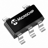
TC1223-3.3VCTTR Microchip Technology, TC1223-3.3VCTTR Datasheet - Page 5

TC1223-3.3VCTTR
Manufacturer Part Number
TC1223-3.3VCTTR
Description
IC CMOS LDO 3.3V 50MA SOT23A-5
Manufacturer
Microchip Technology
Datasheet
1.TC1223-4.0VCTTR.pdf
(14 pages)
Specifications of TC1223-3.3VCTTR
Regulator Topology
Positive Fixed
Voltage - Output
3.3V
Voltage - Input
Up to 6V
Voltage - Dropout (typical)
0.085V @ 50mA
Number Of Regulators
1
Current - Output
50mA (Min)
Operating Temperature
-40°C ~ 125°C
Mounting Type
Surface Mount
Package / Case
SOT-23-5, SC-74A, SOT-25
Number Of Outputs
1
Polarity
Positive
Input Voltage Max
6 V
Output Voltage
3.3 V
Output Type
Fixed
Dropout Voltage (max)
250 mV
Output Current
50 mA
Line Regulation
0.05 %
Load Regulation
0.5 %
Voltage Regulation Accuracy
0.5 %
Maximum Operating Temperature
+ 125 C
Mounting Style
SMD/SMT
Minimum Operating Temperature
- 40 C
Lead Free Status / RoHS Status
Lead free / RoHS Compliant
Current - Limit (min)
-
Lead Free Status / Rohs Status
Lead free / RoHS Compliant
Other names
TC12233.3VCTTR
Available stocks
Company
Part Number
Manufacturer
Quantity
Price
Company:
Part Number:
TC1223-3.3VCTTR
Manufacturer:
ST
Quantity:
45 000
Part Number:
TC1223-3.3VCTTR
Manufacturer:
MICROCHIP/微芯
Quantity:
20 000
4.0
4.1
Integrated thermal protection circuitry shuts the
regulator off when die temperature exceeds 160°C.
The regulator remains off until the die temperature
drops to approximately 150°C.
4.2
The amount of power the regulator dissipates is
primarily a function of input and output voltage, and
output current. The following equation is used to
calculate worst case actual power dissipation:
EQUATION 4-1:
The maximum allowable power dissipation (Equation
4-2) is a function of the maximum ambient temperature
(T
(T
(θ
approximately 220°C/Watt.
EQUATION 4-2:
©
A
JA
J
2002 Microchip Technology Inc.
MAX
MAX
Where:
). The 5-Pin SOT-23A package has a θ
I
V
LOAD
V
) and the thermal resistance from junction-to-air
), the maximum allowable die temperature
OUT
Where all terms are previously defined.
IN
THERMAL CONSIDERATIONS
Thermal Shutdown
Power Dissipation
MAX
MAX
P
MIN
D
= Worst case actual power dissipation
= Maximum voltage on V
= Minimum regulator output voltage
= Maximum output (load) current
P
P
D
D
≈ (V
MAX
IN
= (T
MAX
J
MAX
– V
θ
– T
OUT
JA
A
MIN
MAX
)I
LOAD
IN
)
MAX
JA
of
Equation 4-1 can be used in conjunction with Equation
4-2 to ensure regulator thermal operation is within
limits. For example:
Given:
Find: 1. Actual power dissipation
Actual power dissipation:
P
Maximum allowable power dissipation:
In this example, the TC1223 dissipates a maximum of
26.7mW; below the allowable limit of 318mW. In a
similar manner, Equation 4-1 and Equation 4-2 can be
used to calculate maximum current and/or input
voltage limits.
4.3
The primary path of heat conduction out of the package
is via the package leads. Therefore, layouts having a
ground plane, wide traces at the pads, and wide power
supply bus lines combine to lower θ
increase the maximum allowable power dissipation
limit.
D
≈ (V
= [(3.0 x 1.1) – (2.7 x .975)]40 x 10
= 26.7mW
V
V
I
T
T
P
LOAD
A
OUT
J
IN
D
2. Maximum allowable dissipation
MAX
MAX
MAX
IN
MAX
Layout Considerations
MAX
MIN
MAX
= (125 – 55)
= 318mW
= (T
– V
TC1223/TC1224
= 3.0V ±10%
= 2.7V – 2.5%
= 40mA
= 125°C
= 55°C
J
220
MAX
OUT
θ
– T
MIN
JA
)I
A
MAX
LOAD
)
MAX
JA
–3
DS21368B-page 5
and therefore


