LP3986TLX-2929/NOPB National Semiconductor, LP3986TLX-2929/NOPB Datasheet - Page 9
LP3986TLX-2929/NOPB
Manufacturer Part Number
LP3986TLX-2929/NOPB
Description
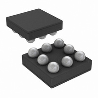
IC REG LDO DUAL 150MA 8MICROSMD
Manufacturer
National Semiconductor
Datasheet
1.LP3986TL-2518NOPB.pdf
(12 pages)
Specifications of LP3986TLX-2929/NOPB
Regulator Topology
Positive Fixed
Voltage - Output
2.9V
Voltage - Input
2.7 ~ 6 V
Voltage - Dropout (typical)
0.06V @ 150mA
Number Of Regulators
2
Current - Output
150mA
Current - Limit (min)
300mA
Operating Temperature
-40°C ~ 125°C
Mounting Type
Surface Mount
Package / Case
8-MicroSMD
Dc
N/A
Lead Free Status / RoHS Status
Lead free / RoHS Compliant
Other names
*LP3986TLX-2929/NOPB
LP3986TLX-2929
LP3986TLX-2929
Available stocks
Company
Part Number
Manufacturer
Quantity
Price
Company:

Part Number:
LP3986TLX-2929/NOPB
Manufacturer:
Texas Instruments
Quantity:
10 000


Application Hints
EXTERNAL CAPACITORS
Like any low-dropout regulator, the LP3986 requires external
capacitors for regulator stability. The LP3986 is specifically
designed for portable applications requiring minimum board
space and smallest components. These capacitors must be
correctly selected for good performance.
INPUT CAPACITOR
An input capacitance of
LP3986 input pin and ground (the amount of the capacitance
may be increased without limit).
This capacitor must be located a distance of not more than
1cm from the input pin and returned to a clean analog ground.
Any good quality ceramic, tantalum, or film capacitor may be
used at the input.
Important: Tantalum capacitors can suffer catastrophic fail-
ures due to surge current when connected to a low-
impedance source of power (like a battery or a very large
capacitor). If a tantalum capacitor is used at the input, it must
be guaranteed by the manufacturer to have a surge current
rating sufficient for the application.
There are no requirements for the ESR on the input capacitor,
but tolerance and temperature coefficient must be considered
when selecting the capacitor to ensure the capacitance will
be
OUTPUT CAPACITOR
The LP3986 is designed specifically to work with very small
ceramic output capacitors, any ceramic capacitor (tempera-
ture characteristics X7R, X5R, Z5U or Y5V) in 1 to 22 µF
range with 5mΩ to 500mΩ ESR range is suitable in the
LP3986 application circuit.
It may also be possible to use tantalum or film capacitors at
the output, but these are not as attractive for reasons of size
and cost (see next section Capacitor Characteristics).
The output capacitor must meet the requirement for minimum
amount of capacitance and also have an ESR (Equivalent
Series Resistance) value which is within a stable range.
NO-LOAD STABILITY
The LP3986 will remain stable and in regulation with no-load
(other than the internal voltage divider). This is specially im-
portant in CMOS RAM keep-alive applications.
CAPACITOR CHARACTERISTICS
The LP3986 is designed to work with ceramic capacitors on
the output to take advantage of the benefits they offer: for
capacitance values in the range of 1µF to 4.7µF range, ce-
ramic capacitors are the smallest, least expensive and have
the lowest ESR values (which makes them best for eliminat-
ing high frequency noise). The ESR of a typical 1µF ceramic
capacitor is in the range of 20 mΩ to 40 mΩ, which easily
meets the ESR requirement for stability by the LP3986.
The ceramic capacitor's capacitance can vary with tempera-
ture. The capacitor type X7R, which operates over a temper-
ature range of -55°C to +125°C, will only vary the capacitance
to within ±15%. Most large value ceramic capacitors (
are manufactured with Z5U or Y5V temperature characteris-
tics. Their capacitance can drop by more than 50% as the
temperature goes from 25°C to 85°C. Therefore, X7R is rec-
ommended over Z5U and Y5 in applications where the am-
bient temperature will change significantly above or below 25°
C.
≊
1µF over the entire operating temperature range.
≊
1µF is required between the
≊
2.2µF)
9
Tantalum capacitors are less desirable than ceramic for use
as output capacitors because they are more expensive when
comparing equivalent capacitance and voltage ratings in the
1µF to 4.7µF range.
Another important consideration is that tantalum capacitors
have higher ESR values than equivalent size ceramics. This
means that while it may be possible to find a tantalum capac-
itor with an ESR value within the stable range, it would have
to be larger in capacitance (which means bigger and more
costly ) than a ceramic capacitor with the same ESR value. It
should also be noted that the ESR of a typical tantalum will
increase about 2:1 as the temperature goes from 25°C down
to −40°C, so some guard band must be allowed.
NOISE BYPASS CAPACITOR
Connecting a 0.01µF capacitor between the C
ground significantly reduces noise on the regulator output.
This cap is connected directly to a high impedance node in
the band gap reference circuit. Any significant loading on this
node will cause a change on the regulated output voltage. For
this reason, DC leakage current through this pin must be kept
as low as possible for best output voltage accuracy. The use
of this 0.01µF bypass capacitor is strongly recommended to
prevent overshoot on the output during start up.
The types of capacitors best suited for the noise bypass ca-
pacitor are ceramic and film. High-quality ceramic capacitors
with either NPO or COG dielectric typically have very low
leakage. Polypropolene and polycarbonate film capacitors
are available in small surface-mount packages and typically
have extremely low leakage current.
Unlike many other LDO's, addition of a noise reduction ca-
pacitor does not effect the transient response of the device.
ON/OFF INPUT OPERATION
The LP3986 is turned off by pulling the V
on by pulling it high. If this feature is not used, the V
should be tied to V
times. To assure proper operation, the signal source used to
drive the V
the specified turn-on/off voltage thresholds listed in the Elec-
trical Characteristics section under V
FAST ON-TIME
The LP3986 outputs are turned on after V
its final value (1.23V nominal). To speed up this process, the
noise reduction capacitor at the bypass pin is charged with an
internal 70µA current source. The current source is turned off
when the bandgap voltage reaches approximately 95% of its
final value. The turn on time is determined by the time con-
stant of the bypass capccitor. The smaller the capacitor value,
the shorter the turn on time, but less noise gets reduced. As
a result, turn on time and noise reduction need to be taken
into design consideration when choosing the value of the by-
pass capacitor.
MICRO SMD MOUNTING
The micro SMD package requires specific mounting tech-
niques which are detailed in National Semiconductor Appli-
cation Note (AN-1112). Referring to the section Surface
Mount Technology (SMT) Assembly Considerations.
For best results during assembly, alignment ordinals on the
PC board may be used to facilitate placement of the micro
SMD device.
EN
input must be able to swing above and below
IN
to keep the regulator output on at all
IL
and V
EN
pin low, and turned
ref
voltage reaches
IH
BYPASS
.
www.national.com
pin and
EN
pin
Related parts for LP3986TLX-2929/NOPB
Image
Part Number
Description
Manufacturer
Datasheet
Request
R

Part Number:
Description:
IC REG LDO DUAL 150MA 8MICROSMD
Manufacturer:
National Semiconductor
Datasheet:
Part Number:
Description:
IC REG LDO DUAL 150MA 8MICROSMD
Manufacturer:
National Semiconductor
Datasheet:
Part Number:
Description:
IC REG LDO DUAL 150MA 8MICROSMD
Manufacturer:
National Semiconductor
Datasheet:
Part Number:
Description:
IC REG LDO DUAL 150MA 8MICROSMD
Manufacturer:
National Semiconductor
Datasheet:
Part Number:
Description:
IC REG LDO DUAL 150MA 8MICROSMD
Manufacturer:
National Semiconductor
Datasheet:
Part Number:
Description:
IC REG LDO DUAL 150MA 8MICROSMD
Manufacturer:
National Semiconductor
Datasheet:
Part Number:
Description:
IC REG LDO DUAL 150MA 8-USMD
Manufacturer:
National Semiconductor
Datasheet:
Part Number:
Description:
IC REG LDO DUAL 150MA 8-USMD
Manufacturer:
National Semiconductor
Datasheet:
Part Number:
Description:
IC REG LDO DUAL 150MA 8-USMD
Manufacturer:
National Semiconductor
Datasheet:
Part Number:
Description:
IC REG LDO DUAL 150MA 8-USMD
Manufacturer:
National Semiconductor
Datasheet:
Part Number:
Description:
IC REG LDO DUAL 150MA 8-USMD
Manufacturer:
National Semiconductor
Datasheet:

Part Number:
Description:
Dual Micropower 150 mA Ultra Low-Dropout CMOS Voltage Regulators in micro SMD Package
Manufacturer:
National Semiconductor
Datasheet:
Part Number:
Description:
Manufacturer:
National Semiconductor
Datasheet:
Part Number:
Description:
Manufacturer:
National Semiconductor
Datasheet:
Part Number:
Description:
IC REG LDO DUAL 150MA 8-MICROSMD
Manufacturer:
National Semiconductor
Datasheet: