NCV1117DT18RKG ON Semiconductor, NCV1117DT18RKG Datasheet - Page 17
NCV1117DT18RKG
Manufacturer Part Number
NCV1117DT18RKG
Description
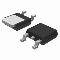
IC REG LDO POS 1A 1.8V DPAK
Manufacturer
ON Semiconductor
Datasheet
1.NCV1117ST50T3G.pdf
(18 pages)
Specifications of NCV1117DT18RKG
Regulator Topology
Positive Fixed
Voltage - Output
1.8V
Voltage - Input
Up to 20V
Voltage - Dropout (typical)
1.07V @ 800mA
Number Of Regulators
1
Current - Limit (min)
1A
Operating Temperature
-40°C ~ 125°C
Mounting Type
Surface Mount
Package / Case
TO-252-2, DPak (2 Leads + Tab), TO-252AA, SC-63
Number Of Outputs
1
Polarity
Positive
Input Voltage Max
20 V
Output Voltage
1.8 V
Output Type
Fixed
Dropout Voltage (max)
1.1 V at 100 mA
Output Current
1 A
Line Regulation
0.4 mV
Load Regulation
2.6 mV
Voltage Regulation Accuracy
1 %
Maximum Operating Temperature
+ 125 C
Mounting Style
SMD/SMT
Minimum Operating Temperature
- 40 C
Lead Free Status / RoHS Status
Lead free / RoHS Compliant
Current - Output
-
Lead Free Status / Rohs Status
Lead free / RoHS Compliant
Available stocks
Company
Part Number
Manufacturer
Quantity
Price

Part Number:
NCV1117DT18RKG
Manufacturer:
ON/安森美
Quantity:
20 000


É É É É É É É
Ç Ç Ç Ç Ç Ç Ç
É É É É É É É
Ç Ç Ç Ç Ç Ç Ç
b2
0.1
M
SECTION B−B
C
H
A
(b2)
b3
S
B
S
A
4
*For additional information on our Pb−Free strategy and soldering
details, please download the ON Semiconductor Soldering and
Mounting Techniques Reference Manual, SOLDERRM/D.
0.2
B
B
E1
M
0.079
E
2.0
A
A
C
L
0.079
B
2.0
PACKAGE DIMENSIONS
SOLDERING FOOTPRINT*
S
0.059
1.5
B
1
2
http://onsemi.com
3
e
T
0.091
CASE 318H−01
2.3
ST SUFFIX
e1
SOT−223
ISSUE O
0.15
3.8
17
c1
0.091
SECTION A−A
2.3
É É É
Ç Ç Ç
É É É
Ç Ç Ç
SCALE 6:1
(b)
b1
C
A1
0.08
A
0.248
6.3
c
inches
mm
NOTES:
1. DIMENSIONS ARE IN MILLIMETERS.
2. INTERPRET DIMENSIONS AND TOLERANCES
3. DIMENSION E1 DOES NOT INCLUDE INTERLEAD
4. DIMENSIONS b AND b2 DO NOT INCLUDE
5. TERMINAL NUMBERS ARE SHOWN FOR
6. DIMENSIONS D AND E1 ARE TO BE DETERMINED
PER ASME Y14.5M, 1994.
FLASH OR PROTRUSION. INTERLEAD FLASH OR
PROTRUSION SHALL NOT EXCEED 0.23 PER
SIDE.
DAMBAR PROTRUSION. ALLOWABLE DAMBAR
PROTRUSION SHALL BE 0.08 TOTAL IN EXCESS
OF THE b AND b2 DIMENSIONS AT MAXIMUM
MATERIAL CONDITION.
REFERENCE ONLY.
AT DATUM PLANE H.
DIM
A1
b1
b2
b3
c1
E1
e1
T
A
b
D
E
L
c
e
MILLIMETERS
MIN
0.02
0.60
0.60
2.90
2.90
0.24
0.24
6.30
6.70
3.30
0.25
---
0
_
2.30
4.60
MAX
1.80
0.11
0.88
0.80
3.10
3.05
0.35
0.30
6.70
7.30
3.70
---
10
_
Related parts for NCV1117DT18RKG
Image
Part Number
Description
Manufacturer
Datasheet
Request
R

Part Number:
Description:
ON Semiconductor [VOLTAGE REGULATOR]
Manufacturer:
ON Semiconductor
Datasheet:
Part Number:
Description:
357-036-542-201 CARDEDGE 36POS DL .156 BLK LOPRO
Manufacturer:
ON Semiconductor
Datasheet:
Part Number:
Description:
357-036-542-201 CARDEDGE 36POS DL .156 BLK LOPRO
Manufacturer:
ON Semiconductor
Datasheet:
Part Number:
Description:
357-036-542-201 CARDEDGE 36POS DL .156 BLK LOPRO
Manufacturer:
ON Semiconductor
Datasheet:
Part Number:
Description:
357-036-542-201 CARDEDGE 36POS DL .156 BLK LOPRO
Manufacturer:
ON Semiconductor
Datasheet:
Part Number:
Description:
357-036-542-201 CARDEDGE 36POS DL .156 BLK LOPRO
Manufacturer:
ON Semiconductor
Datasheet:
Part Number:
Description:
357-036-542-201 CARDEDGE 36POS DL .156 BLK LOPRO
Manufacturer:
ON Semiconductor
Datasheet:
Part Number:
Description:
357-036-542-201 CARDEDGE 36POS DL .156 BLK LOPRO
Manufacturer:
ON Semiconductor
Datasheet:
Part Number:
Description:
357-036-542-201 CARDEDGE 36POS DL .156 BLK LOPRO
Manufacturer:
ON Semiconductor
Datasheet:
Part Number:
Description:
357-036-542-201 CARDEDGE 36POS DL .156 BLK LOPRO
Manufacturer:
ON Semiconductor
Datasheet:
Part Number:
Description:
357-036-542-201 CARDEDGE 36POS DL .156 BLK LOPRO
Manufacturer:
ON Semiconductor
Datasheet:
Part Number:
Description:
Manufacturer:
ON Semiconductor
Datasheet:
Part Number:
Description:
Manufacturer:
ON Semiconductor
Datasheet:
Part Number:
Description:
Manufacturer:
ON Semiconductor
Datasheet: