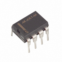
MAX603CPA Maxim Integrated Products, MAX603CPA Datasheet - Page 9

MAX603CPA
Manufacturer Part Number
MAX603CPA
Description
IC LDO REG LOW-IQ 5V/ADJ 8-DIP
Manufacturer
Maxim Integrated Products
Datasheet
1.MAX603CSA.pdf
(12 pages)
Specifications of MAX603CPA
Regulator Topology
Positive Fixed or Adjustable
Voltage - Output
5V, 1.25 ~ 11 V
Voltage - Input
2.7 ~ 11.5 V
Voltage - Dropout (typical)
0.32V @ 500mA
Number Of Regulators
1
Current - Output
500mA
Operating Temperature
0°C ~ 70°C
Mounting Type
Through Hole
Package / Case
8-DIP (0.300", 7.62mm)
Number Of Outputs
1
Polarity
Positive
Input Voltage Max
11.5 V
Output Voltage
1.25 V to 11 V, 5 V
Output Type
Adjustable, Fixed
Dropout Voltage (max)
0.22 V at 200 mA
Output Current
500 mA
Line Regulation
7 mV
Load Regulation
60 mV
Voltage Regulation Accuracy
3 %
Maximum Power Dissipation
0.727 W
Maximum Operating Temperature
+ 70 C
Mounting Style
Through Hole
Minimum Operating Temperature
0 C
Reference Voltage
1.2 V
Lead Free Status / RoHS Status
Contains lead / RoHS non-compliant
Current - Limit (min)
-
Available stocks
Company
Part Number
Manufacturer
Quantity
Price
Company:
Part Number:
MAX603CPA
Manufacturer:
LT
Quantity:
1 106
Part Number:
MAX603CPA
Manufacturer:
MAXIM/美信
Quantity:
20 000
Figure 6. 3.3V or 5V Linear-Regulator Application
Figure 7. Power-Supply Rejection Ratio vs. Ripple Frequency
the more positive of the two. The control circuitry can
then remain functioning and turn the pass transistor off,
limiting reverse currents back through the device. This
feature allows a backup regulator or battery pack to
maintain V
Reverse-current protection activates when the voltage
on IN falls 6mV (20mV maximum) below the voltage on
OUT. Before this happens, currents as high as several
milliamperes can flow back through the device. After
switchover, typical reverse currents are limited to
0.01µA for as long as the condition exists.
BATTERY
90
80
70
60
50
40
30
20
10
OUT
0
10
0
V
FOR f < 400kHz
C
C
when the supply at IN fails.
POWER-SUPPLY REJECTION RATIO
IN
IN
OUT
C
IN
= 1V
= 0 F
10
_______________________________________________________________________________________
= 10 F
1
p-p
10
vs. FREQUENCY
FREQUENCY (Hz)
2
OFF
IN
GND
MAX603
MAX604
10
5V/3.3V or Adjustable, Low-Dropout,
I
3
OUT
I
OUT
= 1mA
10
SET
OUT
= 100mA
4
Low I
10
5
10
6
C
10 F
OUT
VOLTAGE
OUTPUT
Q
, 500mA Linear Regulators
Figure 6 illustrates the typical application for the
MAX603/MAX604.
Normally, use 0.1µF to 10µF capacitors on the input
and 10µF on the output of the MAX603/MAX604. The
larger input capacitor values provide better supply-
noise rejection and line-transient response. Improve
load-transient response, stability, and power-supply
rejection by using large output capacitors. For stable
operation over the full temperature range and with load
currents up to 500mA, 10µF is recommended. Using
capacitors smaller than 3.3µF can result in oscillation.
The MAX603/MAX604 exhibit 3mVp-p to 4mVp-p of
noise during normal operation. This is negligible in most
applications. When using the MAX603/MAX604 in appli-
cations that include analog-to-digital converters of
greater than 12 bits, consider the ADC’s power-supply
rejection specifications. Refer to the output noise plot in
the Typical Operating Characteristics .
The MAX603/MAX604 are designed to deliver low
dropout voltages and low quiescent currents in battery-
powered systems. Achieving these objectives requires
trading off power-supply noise rejection and swift
response to supply variations and load transients.
Power-supply rejection is 80dB at low freqencies and
rolls off above 10Hz. As the frequency increases above
10kHz, the output capacitor is the major contributor to
the rejection of power-supply noise (Figure 7). Do not
use power supplies with ripple above 100kHz, especial-
ly when the ripple exceeds 100mVp-p. When operating
from sources other than batteries, improved supply-
noise rejection and transient response can be achieved
by increasing the values of the input and output capaci-
tors, and through passive filtering techniques. The
Typical Operating Characteristics show the MAX603/
MAX604 supply and load-transient responses.
The Typical Operating Characteristics show the
MAX603/MAX604 load-transient response. Two compo-
nents of the output response can be observed on the
load-transient graphs—a DC shift from the output imped-
ance due to the different load currents, and the transient
response. Typical transients for step changes in the load
current from 5mA to 500mA are 0.2V. Increasing the out-
put capacitor’s value attenuates transient spikes.
__________Applications Information
PSRR and Operation from Sources
Transient Considerations
Capacitor Selection and
Other than Batteries
Regulator Stability
Noise
9


