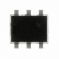
USBLC6-2P6 STMicroelectronics, USBLC6-2P6 Datasheet - Page 7

USBLC6-2P6
Manufacturer Part Number
USBLC6-2P6
Description
IC ESD PROTECTION HS SOT-666
Manufacturer
STMicroelectronics
Datasheet
1.USBLC6-2P6.pdf
(14 pages)
Specifications of USBLC6-2P6
Voltage - Working
5V
Voltage - Clamping
6V
Technology
Mixed Technology
Number Of Circuits
2
Applications
USB
Package / Case
SC-89-6, SOT-563F, SOT-666
Polarity
Bidirectional
Channels
2 Channels
Clamping Voltage
17 V
Operating Voltage
5 V
Breakdown Voltage
6 V
Termination Style
SMD/SMT
Peak Surge Current
5 A
Capacitance
3.5 pF
Maximum Operating Temperature
+ 125 C
Minimum Operating Temperature
- 40 C
Dimensions
1.7 mm W x 1.7 mm L x 0.6 mm H
Diode Type
Low Capacitance / ESD Protection
Clamping Voltage Vc Max
17V
Diode Case Style
SOT-666
No. Of Pins
6
Rohs Compliant
Yes
Operating Temperature Min Deg. C
-40C
Operating Temperature Max Deg. C
125C
Lead Free Status / RoHS Status
Lead free / RoHS Compliant
Power (watts)
-
Lead Free Status / Rohs Status
Lead free / RoHS Compliant
Other names
497-5026-2
Available stocks
Company
Part Number
Manufacturer
Quantity
Price
Company:
Part Number:
USBLC6-2P6
Manufacturer:
Keystone
Quantity:
30 000
Part Number:
USBLC6-2P6
Manufacturer:
ST
Quantity:
20 000
USBLC6-2
Figure 12. Analog crosstalk measurements
Figure 12.
range of analog signals (up to 240 MHz) the effect on disturbed line is less than -55 db ( see
Figure
Figure 13. Analog crosstalk results
As the USBLC6-2 is designed to protect high speed data lines, it must ensure a good
transmission of operating signals. The frequency response
information and shows that the USBLC6-2 is well suitable for data line transmission up to
480 Mbit/s while it works as a filter for undesirable signals like GSM (900 MHz) frequencies,
for instance.
13.).
NETWORK ANALYSER
shows the measurement circuit for the analog application. In usual frequency
PORT 1
- 120.00
- 30.00
- 60.00
- 90.00
0.00
100.0k
dB
1.0M
TEST BOARD
10.0M
100.0M
Vbus
F (Hz)
(Figure
1.0G
NETWORK ANALYSER
5.) gives attenuation
Technical information
PORT 2
7/14


