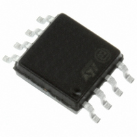
LCP02-150B1 STMicroelectronics, LCP02-150B1 Datasheet - Page 7

LCP02-150B1
Manufacturer Part Number
LCP02-150B1
Description
SURGE SUPPRES IC FOR SLICS 8SOIC
Manufacturer
STMicroelectronics
Datasheet
1.LCP02-150B1RL.pdf
(10 pages)
Specifications of LCP02-150B1
Technology
Mixed Technology
Number Of Circuits
1
Applications
SLIC
Package / Case
8-SOIC (5.3mm Width), 8-SOP, 8-SOEIAJ
Mounting Style
SMD/SMT
Lead Free Status / RoHS Status
Lead free / RoHS Compliant
Power (watts)
-
Voltage - Working
-
Voltage - Clamping
-
Lead Free Status / Rohs Status
Lead free / RoHS Compliant
Other names
497-2558-5
Available stocks
Company
Part Number
Manufacturer
Quantity
Price
Part Number:
LCP02-150B1RL
Manufacturer:
ST
Quantity:
20 000
LCP02-150B1
The series resistors Rs1 and Rs2 designed in
PTCs which are needed to withstand the power contact or the power induction tests
imposed by the country standards. Taking this factor into account, the actual lightning surge
current flowing through the LCP02-150B1 is equal to :
With
For a line card with 50 Ω of series resistors which has to be qualified under Bellcore 1000 V
10/1000 µs surge, the present current through the LCP02-150B1 is equal to :
The LCP02-150B1 topology is particularly optimized for the new telecom applications such
as fiber in the loop, WLL systems, decentralized central office for example.
Figure 8.
Figure 8
battery voltages. With such a protection the SLIC is protected against surge over +Vb and
lower than -Vbat. In this case, +Vb can be programmed up to +120 V while -Vbat can be
programmed down to -120 V.
I surge = Vsurge / (Rg + Rs)
V surge = peak surge voltage imposed by the standard.
Rg = series resistor of the surge generator
Rs = series resistor of the line card (e.g. PTC)
I surge = 1000 / (10 + 50) = 17 A
Line
shows the classical protection topology for SLIC using both positive and negative
Protection of SLIC with positive and negative battery voltages
Rs (*) = PTC or Resistor fuse
Line card
GND
Rs (*)
Rs (*)
220nF
Doc ID 7275 Rev 6
Gn
LCP02
RING
TIP
Figure 7
Gp
represent the fuse resistors or the
220nF
Technical information
+Vb
-Vbat
SLIC
TIP
RING
7/10


