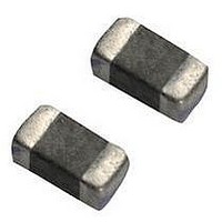
VC080530A650RP AVX Corporation, VC080530A650RP Datasheet - Page 2

VC080530A650RP
Manufacturer Part Number
VC080530A650RP
Description
TVS CERAMIC 30V 0805 SMD
Manufacturer
AVX Corporation
Series
TransGuard®r
Specifications of VC080530A650RP
Varistor Voltage
41V
Current-surge
30A
Number Of Circuits
1
Maximum Ac Volts
21VAC
Maximum Dc Volts
30VDC
Energy
0.10J
Package / Case
0805 (2012 Metric)
Suppressor Type
Transient Voltage
Peak Surge Current @ 8/20µs
30A
Varistor Case
0805
Clamping Voltage Vc Max
67V
Peak Energy (10/1000us)
0.1J
Voltage Rating Vdc
30V
Voltage Rating Vac
21V
Product
MLV
Voltage Rating Dc
30 V
Clamping Voltage
67 V
Surge Energy Rating
0.1 J
Capacitance
90 pF
Operating Temperature Range
- 55 C to + 125 C
Mounting
SMD/SMT
Dimensions
2.01 mm L
Lead Free Status / RoHS Status
Lead free / RoHS Compliant
Lead Free Status / RoHS Status
Lead free / RoHS Compliant, Lead free / RoHS Compliant
Available stocks
Company
Part Number
Manufacturer
Quantity
Price
Company:
Part Number:
VC080530A650RP
Manufacturer:
AVX
Quantity:
8 000
Part Number:
VC080530A650RP
Manufacturer:
AVX
Quantity:
20 000
HOW TO ORDER
ELECTRICAL CHARACTERISTICS PER ELEMENT
MultiGuard
60
MultiGuard TVS Array
AVX Multilayer Ceramic Transient Voltage Suppression
Arrays – ESD Protection for CMOS and Bi Polar Systems
2 Element
0405 Chip
2 Element
0508 Chip
4 Element
0508 Chip
4 Element
0612 Chip
MG
04 = 0405
05 = 0508
06 = 0612
MG042S05X150 _ _
MG052S05A150 _ _
MG052S09A200 _ _
MG052S14A300 _ _
MG052S18A400 _ _
MG054S05X150 _ _
MG054S09X200 _ _
MG054S14X300 _ _
MG054S18X400 _ _
MG064S05A150 _ _
MG064S09A200 _ _
MG064S14A300 _ _
MG064S18A400 _ _
MG042L14V400 _ _
MG042L18V500 _ _
MG052L18X500 _ _
MG054L18V500 _ _
MG064L18X500 _ _
Case
Size
Part Number
04
AVX
Configuration
2 = 2 Elements
4 = 4 Elements
2
Termination Finish Code
Packaging Code
Working Working Breakdown Clamping
Voltage
≤18.0
≤18.0
≤18.0
(DC)
14.0
18.0
14.0
18.0
14.0
18.0
14.0
18.0
5.6
9.0
5.6
9.0
5.6
9.0
5.6
S = Standard
L = Low
AVX’s Transient Voltage Suppression (TVS) Arrays address six trends in today’s electronic
circuits: (1) mandatory ESD protection, (2) mandatory EMI control, (3) signal integrity
improvement, (4) PCB downsizing, (5) reduced component placement costs, and (6) pro-
tection from induced slow speed transient voltages and currents.
AVX’s MultiGuard products offer numerous advantages, which include a faster turn-on-time
(<1nS), repetitive strike capability, and space savings. In some cases, MultiGuard consumes
less than 75% of the PCB real estate required for the equivalent number of discrete chips.
This size advantage, coupled with the savings associated with placing only one chip,
makes MultiGuard the TVS component of choice for ESD protection of I/O lines in portable
equipment and programming ports in cellular phones. Other applications include differential
data line protection, ASIC protection and LCD driver protection for portable computing
devices.
Where multiple lines require the ESD protection, the 4-element 0612 or 0508 chip is an
ideal solution. While the 2-element 0405 MultiGuard is the smallest TVS array, the 4-ele-
ment 0508 MultiGuard is the smallest 4-element TVS device available in the market today.
Available with standard working voltage of 5.6V up to 18V with low capacitance in the 3
case sizes, AVX MultiGuard arrays offer a very broad range of integrated TVS solutions to
the design community.
Capacitance
Voltage
Construction
≤14.0
≤14.0
≤14.0
Style
10.0
14.0
(AC)
10.0
14.0
10.0
14.0
10.0
14.0
4.0
4.0
6.4
4.0
6.4
4.0
6.4
L
18.5±12%
12.7±15%
19.5±12%
25.5±10%
12.7±15%
19.5±12%
25.5±10%
12.7±15%
19.5±12%
25.5±10%
8.5±20%
8.5±20%
8.5±20%
8.5±20%
Voltage
V
V
V
W
W
05 = 5.6VDC
09 = 9.0VDC
14 = 14.0VDC
18 = 18.0VDC
N/A
N/A
N/A
N/A
B
V
(DC)
(AC)
Tol
B
Working
Voltage
14
DC Working Voltage (V)
AC Working Voltage (V)
Typical Breakdown Voltage
(V @ 1mA
V
B
Tolerance is ± from Typical Value
Voltage
DC
18
32
50
18
22
32
42
50
18
22
32
42
50
18
22
32
42
50
)
A = 0.10 Joules
V = 0.02 Joules
X = 0.05 Joules
Energy
Rating
A
Current
For V
Test
1
1
1
1
1
1
1
1
1
1
1
1
1
1
1
1
1
1
C
Clamping
Maximum
150 = 18V
200 = 22V
300 = 32V
400 = 42V
500 = 50V
Leakage
Voltage
Current
300
Cap
35
15
10
35
25
15
10
10
35
25
15
10
10
35
25
15
10
10
V
I
E
I
I
VC
P
L
C
T
Clamping Voltage (V @ I
Test Current for V
Maximum Leakage Current at the Working Voltage (µA)
Transient Energy Rating (J, 10x1000µS)
Peak Current Rating (A, 8x20µS)
Typical Capacitance (pF) @ 1MHz and 0.5 V
Transient
(PCS/REEL)
Packaging
Energy
Rating
D = 1,000
R = 4,000
T = 10,000
0.05
0.02
0.02
0.10
0.10
0.10
0.10
0.10
0.05
0.05
0.05
0.05
0.02
0.10
0.10
0.10
0.05
0.10
T
C
(A, 8x20µS)
Current
Rating
VC
Peak
)
M = Ni/Sn Pb (Plated)
P = Ni/Sn Alloy
15
15
15
30
30
30
30
20
15
15
15
15
15
30
30
30
15
20
(Plated)
Termination
Finish
Typical
P
Cap
825
550
425
225
400
300
150
120
825
550
425
120
300
50
50
75
45
40
RMS


