TMOV34S551MX2696 Littelfuse Inc, TMOV34S551MX2696 Datasheet - Page 5
TMOV34S551MX2696
Manufacturer Part Number
TMOV34S551MX2696
Description
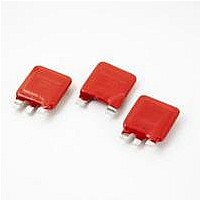
VARISTOR THERMAL 550V 40KA 20MM
Manufacturer
Littelfuse Inc
Series
TMOV34S®r
Specifications of TMOV34S551MX2696
Energy
735J
Varistor Voltage
939V
Current-surge
40kA
Number Of Circuits
1
Maximum Ac Volts
550VAC
Maximum Dc Volts
700VDC
Package / Case
34mm Square 3-Lead
Technology
Metal Oxide
Capacitance Value
2250pF
Clamping Current
200A
Clamping Voltage
1415V
Ac Voltage Rating (max)
550VAC
Dc Voltage Rating (max)
700VDC
Operating Temp Range
-55C to 85C
Mounting
Through Hole
Surge Current (max)
40000A
Product Length (mm)
37mm
Product Depth (mm)
15.6mm
Product Height (mm)
42.5mm
Product
MOV
Voltage Rating Dc
700 V
Voltage Rating Ac
550 V
Peak Surge Current
40 KA
Surge Energy Rating
735 J
Capacitance
2250 pF
Operating Temperature Range
- 55 C to + 85 C
Current Rating
40000 A
Dimensions
37 mm L x 14.8 mm H
Tolerance
20 %
Lead Free Status / RoHS Status
Contains lead / RoHS non-compliant
Lead Free Status / RoHS Status
Compliant, Contains lead / RoHS non-compliant


©2008 Littelfuse, Inc.
Specifications are subject to change without notice.
Please refer to www.littelfuse.com/series/tmov34s.html for current information.
Lead Configurations
TMOV34S
The application examples below show how the monitor lead on the TMOV34S
element has been opened. This signifies that the circuit is no longer protected from transients by the MOV.
Application Example 1
thermal element opens.
Application Example 2
This circuit utilizes an optocoupler to provide
galvanic isolations between the TMOV34S
varistor and the indicating or alarm circuitry.
Line
Line Fuse
Neutral
Line
Line Fuse
Neutral
TMOV34S “M”
®
Varistor
TMOV34S “M”
Varistor Application Examples
TMOV34S
Varistor
®
"E" 2-Lead Varistor
LED
R
R
AC OPTOCOUPLER
Thermal
Fuse
Element
MOV
Varistor Products
Industrial High Energy Thermally Protected Varistors > TMOV34S
®
TO STATUS
ANNUNCIATOR
LIGHT/ALARM
Revision: February 9, 2009
159
Application Example 3
This circuit illustrates the use of the monitoring lead of
the TMOV34S
operated when overvoltage protection present. In normal
operation the load switch relay solenoid is powered via the
monitor lead of the TMOV34S
illuminate.
guideline only. Verification of actual indicator circuitry
values selected must be appropriate for the specific
Line
Line Fuse
Neutral
TMOV34S “M”
®
TMOV34S
Varistor
can be used to indicate that the thermal
®
1
varistor to ensure that equipment is only
2
®
Monitor Lead
3
"M" 3-Lead Varistor
Fault LED
(Normallyoff)
®
varistor. In the event of the
2
1
3
Load Switch Relay
(loss of protection)
Monitor Lead
TMOV34S
Thermal
Fuse
Element
R
"Load Powered"
neon lamp
MOV
®
Varistor Series
®
Series
Related parts for TMOV34S551MX2696
Image
Part Number
Description
Manufacturer
Datasheet
Request
R

Part Number:
Description:
VARISTOR THERMAL 575V 40KA 20MM
Manufacturer:
Littelfuse Inc
Datasheet:
Part Number:
Description:
VARISTOR THERMAL 480V 40KA 20MM
Manufacturer:
Littelfuse Inc
Datasheet:
Part Number:
Description:
VARISTOR THERMAL 510V 40KA 20MM
Manufacturer:
Littelfuse Inc
Datasheet:
Part Number:
Description:
VARISTOR THERMAL 750V 40KA 20MM
Manufacturer:
Littelfuse Inc
Datasheet:
Part Number:
Description:
VARISTOR THERMAL 460V 40KA 20MM
Manufacturer:
Littelfuse Inc
Datasheet:
Part Number:
Description:
VARISTOR THERMAL 660V 40KA 20MM
Manufacturer:
Littelfuse Inc
Datasheet:

Part Number:
Description:
VARISTOR THERMAL 460V 40KA 34MM
Manufacturer:
Littelfuse Inc
Datasheet:
Part Number:
Description:
VARISTOR THERMAL 480V 40KA 34MM
Manufacturer:
Littelfuse Inc
Datasheet:
Part Number:
Description:
VARISTOR THERMAL 510V 40KA 34MM
Manufacturer:
Littelfuse Inc
Datasheet:
Part Number:
Description:
VARISTOR THERMAL 510V 40KA 34MM
Manufacturer:
Littelfuse Inc
Datasheet:

Part Number:
Description:
FUSEHOLDER 20A MINI INLINE CRIMP
Manufacturer:
Littelfuse Inc
Datasheet:

Part Number:
Description:
FUSEHOLDER BODY ATO INLINE PNLMT
Manufacturer:
Littelfuse Inc
Datasheet:

Part Number:
Description:
FUSE 2A 63V FAST 1206
Manufacturer:
Littelfuse Inc
Datasheet:
Part Number:
Description:
FUSE 1.25A 63V FAST 1206
Manufacturer:
Littelfuse Inc
Datasheet:
Part Number:
Description:
FUSE .250A 125V FAST 1206
Manufacturer:
Littelfuse Inc
Datasheet: