V131DA40 Littelfuse Inc, V131DA40 Datasheet - Page 2
V131DA40
Manufacturer Part Number
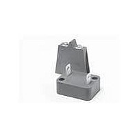
V131DA40
Description
VARISTOR INDUST 130V 270J DA
Manufacturer
Littelfuse Inc
Series
DA/DBr
Type
MOVr
Specifications of V131DA40
Package / Case
Chassis Mount
Number Of Circuits
1
Energy
270J
Current-surge
40kA
Maximum Ac Volts
130VAC
Maximum Dc Volts
175VDC
Varistor Voltage
200V
Voltage Rating Dc
175 V
Voltage Rating Ac
130 V
Clamping Voltage
345 V
Peak Surge Current
40 KA
Capacitance
10000 pF
Operating Temperature Range
- 55 C to + 85 C
Mounting
SMD/SMT
Dimensions
40 mm Dia.
Termination Style
Screw
Brand/series
DA Series
Current, Peak
40000 A
Electric Strength
5000 V
Energy Rating
270 Joules
Mounting Style
Bolt-Down
Package
Screw
Resistance, Insulation
1000 Megohms
Technology
Metal Oxide
Temperature, Operating, Maximum
85 °C
Temperature, Operating, Minimum
-55 °C
Terminal Type
Screw
Voltage, Ac
130 VAC
Voltage, Clamping
345 V
Voltage, Dc
175 VDC
Voltage, Operating
110 VAC (Max.) @ 85 °C
Voltage, Varistor
228
Wide Operating Voltage Range Vmacrms
150 V to 575 V
Lead Free Status / RoHS Status
Contains lead / RoHS non-compliant
Lead Free Status / RoHS Status
Lead free / RoHS Compliant, Contains lead / RoHS non-compliant


DA/DB Varistor Series
Varistor Products
High Energy Industrial
Absolute Maximum Ratings
Continuous:
Transient:
Operating Ambient Temperature Range (T A ) . . . . . . . . . . . . . . . . . . . . . . . . . . . . . . . . . . . . . . . . . . . . . . . . . . . . . . . . . . . . . . . -55 to 85
Storage Temperature Range (T STG ) . . . . . . . . . . . . . . . . . . . . . . . . . . . . . . . . . . . . . . . . . . . . . . . . . . . . . . . . . . . . . . . . . . . . . -55 to 125
Temperature Coefficient (αV) of Clamping Voltage (V C ) at Specified Test Current . . . . . . . . . . . . . . . . . . . . . . . . . . . . . . . . . . . . <0.01
Hi-Pot Encapsulation (Isolation Voltage Capability) . . . . . . . . . . . . . . . . . . . . . . . . . . . . . . . . . . . . . . . . . . . . . . . . . . . . . . . . . . . . 5000
Insulation Resistance . . . . . . . . . . . . . . . . . . . . . . . . . . . . . . . . . . . . . . . . . . . . . . . . . . . . . . . . . . . . . . . . . . . . . . . . . . . . . . . . . . . 1000
CAUTION: Stresses above those listed in “Absolute Maximum Ratings” may cause permanent damage to the device. This is a stress only rating and operation of the device
at these or any other conditions above those indicated in the operational sections of this specification is not implied.
Device Ratings and Specifications
Steady State Applied Voltage:
AC Voltage Range (V M(AC)RMS ) . . . . . . . . . . . . . . . . . . . . . . . . . . . . . . . . . . . . . . . . . . . . . . . . . . . . . . . . . . . . . . . . . . . . . 130 to 750
DC Voltage Range (V M(DC) ) . . . . . . . . . . . . . . . . . . . . . . . . . . . . . . . . . . . . . . . . . . . . . . . . . . . . . . . . . . . . . . . . . . . . . . . . 175 to 970
Peak Pulse Current (I TM )
For 8/20µs Current Wave (See Figure 2) . . . . . . . . . . . . . . . . . . . . . . . . . . . . . . . . . . . . . . . . . . . . . . . . . . . . . . . . . . . . . . . . . 40,000
Single Pulse Energy Range
For 2ms Current Square Wave (W TM ). . . . . . . . . . . . . . . . . . . . . . . . . . . . . . . . . . . . . . . . . . . . . . . . . . . . . . . . . . . . . . . . . 270 to 1050
(Dielectric must withstand indicated DC voltage for one minute per MIL-STD 202, Method 301)
NOTE: Average power dissipation of transients not to exceed 2.0W.
1: Peak current applies to applications rated up to 115V
2: Peak current applies to applications rated up to 132V
V131DA40
V151DA40
V251DA40
V271DA40
V321DA40
V421DA40
V481DA40
V511DA40
V571DA40
V661DA40
V751DA40
PART NUMBER AND
DEVICE BRANDING
DA
V131DB40
V151DB40
V251DB40
V271DB40
V321DB40
V421DB40
V481DB40
V511DB40
V571DB40
V661DB40
V751DB40
DB
For ratings of individual members of a series, see Device Ratings and Specifications chart
V
V
M(AC)
130
150
250
275
320
420
480
510
575
660
750
CONTINUOUS
(V)
RMS
MAXIMUM RATINGS (85
V
V
M(DC)
175
200
330
369
420
560
640
675
730
850
970
(V)
DC
RMS
RMS
ENERGY
w w w . l i t t e l f u s e . c o m
. Peak Current is 30kA for applications greater than 115V
. Peak Current is 30kA for applications greater than 132V
(2ms)
W
1050
270
300
370
400
460
600
650
700
770
900
(J)
TM
TRANSIENT
o
C)
CURRENT
(8/20µs)
PEAK
40000
40000
40000
40000
40000
40000
40000
40000
40000
40000
40000
(A)
I
TM
1
2
VARISTOR VOLTAGE AT
1080
MIN
(V)
184
212
354
389
462
610
670
735
805
940
1mA DC TEST
CURRENT
V
1050
1200
N(DC)
(V)
200
240
390
430
510
680
750
820
910
SPECIFICATIONS (25
MAX
1000
1160
1320
(V)
228
268
429
473
561
748
825
910
RMS
RMS
DA/DB SERIES
MAX CLAMP-
ING VOLT V
CURRENT
AT 200A
(8/20µs)
.
.
1130
1240
1350
1480
1720
2000
(V)
345
405
650
730
830
V
C
o
C)
C
TYPICAL
CAPACI-
f = 1MHz
TANCE
10000
(pF)
8000
5000
4500
3800
3000
2700
2500
2200
2000
1800
87
UNITS
%/
MΩ
o
o
V
V
A
V
J
C
C
o
C
2
Related parts for V131DA40
Image
Part Number
Description
Manufacturer
Datasheet
Request
R

Part Number:
Description:
FUSEHOLDER 20A MINI INLINE CRIMP
Manufacturer:
Littelfuse Inc
Datasheet:

Part Number:
Description:
FUSEHOLDER BODY ATO INLINE PNLMT
Manufacturer:
Littelfuse Inc
Datasheet:

Part Number:
Description:
FUSE 2A 63V FAST 1206
Manufacturer:
Littelfuse Inc
Datasheet:
Part Number:
Description:
FUSE 1.25A 63V FAST 1206
Manufacturer:
Littelfuse Inc
Datasheet:
Part Number:
Description:
FUSE .250A 125V FAST 1206
Manufacturer:
Littelfuse Inc
Datasheet:
Part Number:
Description:
FUSE 4A 32V FAST 1206
Manufacturer:
Littelfuse Inc
Datasheet:
Part Number:
Description:
FUSE 1.75A 63V FAST 1206
Manufacturer:
Littelfuse Inc
Datasheet:

Part Number:
Description:
FUSE 1A 32V FST 0603 LEADFREE TR
Manufacturer:
Littelfuse Inc
Datasheet:

Part Number:
Description:
FUSE 1A 32V FAST SLIM 0402
Manufacturer:
Littelfuse Inc
Datasheet:

Part Number:
Description:
FUSE 2A 125V FAST NANO2 SMD
Manufacturer:
Littelfuse Inc
Datasheet:

Part Number:
Description:
FUSE .250A 125V FAST NANO2 SMD
Manufacturer:
Littelfuse Inc
Datasheet:

Part Number:
Description:
FUSE .500A 125V FAST NANO2 SMD
Manufacturer:
Littelfuse Inc
Datasheet:

Part Number:
Description:
FUSE 1.5A 125V FAST NANO2 SMD
Manufacturer:
Littelfuse Inc
Datasheet:

Part Number:
Description:
FUSE 4A 125V FAST NANO2 SMD
Manufacturer:
Littelfuse Inc
Datasheet:

Part Number:
Description:
FUSE 1A 125V FAST NANO2 SMD
Manufacturer:
Littelfuse Inc
Datasheet: