HM2J08PE5110N9LF FCI, HM2J08PE5110N9LF Datasheet - Page 2
HM2J08PE5110N9LF
Manufacturer Part Number
HM2J08PE5110N9LF
Description
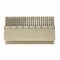
CONN HEADER 125POS 2MM R/A PRSFT
Manufacturer
FCI
Series
Millipacs®r
Type
Br
Datasheet
1.HM2J08PE5110N9LF.pdf
(22 pages)
Specifications of HM2J08PE5110N9LF
Connector Type
Header, Male Pins
Connector Style
B 25
Number Of Positions
125
Number Of Positions Loaded
All
Pitch
0.079" (2.00mm)
Number Of Rows
5
Mounting Type
Through Hole, Right Angle
Termination
Press-Fit
Connector Usage
CompactPCI
Contact Finish
Gold
Contact Finish Thickness
31.5µin (0.80µm)
Current Rating
1.5A
Voltage Rating
500V
Operating Temperature
-55°C ~ 125°C
Product Type
Male
Number Of Positions / Contacts
125
Mounting Angle
Right
Termination Style
Press Fit
Housing Material
Thermoplastic, High Temperature
Contact Material
Phosphor Bronze
Mounting Style
Through Hole
Lead Free Status / RoHS Status
Lead free / RoHS Compliant
Other names
609-2123


TABLE OF CONTENTS
1. OBJECTIVE ..................................................................................................................................................3
2. SCOPE..........................................................................................................................................................3
3. GENERAL.....................................................................................................................................................3
4. DRAWINGS AND APPLICABLE DOCUMENTS.........................................................................................4
5. APPLICATION REQUIREMENTS..................................................................................................................5
6. CODING KEYS .............................................................................................................................................8
7. APPLICATION TOOLING ............................................................................................................................9
8. APPLICATION PROCEDURE....................................................................................................................14
9. COVER SHIELD INSTALLATION..............................................................................................................16
10.
11.
12.
TITLE
Copyright 2001 FCI USA, INC.
Form E-3334 02/12/01
4.1.
5.1.
5.2.
5.3.
7.1.
7.2.
7.3.
9.1.
9.2.
11.1.
11.2.
11.3.
POST-APPLICATION INSPECTION REQUIREMENTS ........................................................................19
REMOVAL TOOLING .............................................................................................................................20
REVISION RECORD ...............................................................................................................................22
Part Numbering Logic.............................................................................................................................4
Shielded right angle receptacle connectors ...........................................................................................5
Shielded right angle Header connector.................................................................................................8
Non-shielded connectors .......................................................................................................................8
Push blade (TOP TOOL)......................................................................................................................11
Anvil (BOTTOM TOOL) ........................................................................................................................11
APPLICATION TOOLING ....................................................................................................................12
One piece cover shield with 5 or 8 row receptacle connectors............................................................17
Clip on Cover Shield with 8 row connectors ........................................................................................18
Millipacs
Removal tooling for the 5+8 row connector.....................................................................................21
Removal tooling for the clip on cover shield ....................................................................................20
Removal tooling for one piece cover shield.....................................................................................20
®
HM 5 and 8 Row Right Angle Signal Receptacles
Millipacs
®
Application Guide
HM Right Angle Headers
TYPE
APPLICATION SPECIFICATION
PDM: Rev:B
STATUS:
NUMBER
PAGE
AUTHORIZED BY
T. De Rooster
Released
2 of 22
UNRESTRICTED
GS-20-022
REVISION
DATE
Printed: Feb 25, 2010
16-May-02
B
GS-01-001
.
Related parts for HM2J08PE5110N9LF
Image
Part Number
Description
Manufacturer
Datasheet
Request
R

Part Number:
Description:
(FCI-HR005 - FCI-HR040) Large Active Area and High Speed Silicon Photodiodes
Manufacturer:
Laser Components
Datasheet:
Part Number:
Description:
(FCI-INGAAS-55 - FCI-INGAAS-500) High Speed InGaAs Photodiodes
Manufacturer:
Laser Components
Datasheet:
Part Number:
Description:
Door, lock & key
Manufacturer:
GAMEWELL-FCI [Gamewell-FCI by Honeywell]
Datasheet:
Part Number:
Description:
30485Fire Fighter Phone Accessories
Manufacturer:
GAMEWELL-FCI Gamewell-FCI by Honeywell
Datasheet:

Part Number:
Description:
Manufacturer:
FCI
Datasheet:
Part Number:
Description:
Manufacturer:
FCI
Datasheet: