PR02000203303JR500 Vishay, PR02000203303JR500 Datasheet - Page 15
PR02000203303JR500
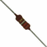
Manufacturer Part Number
PR02000203303JR500
Description
RES 330K OHM METAL FILM 2W 5%
Manufacturer
Vishay
Series
PR02r
Type
High power in small packagesr
Specifications of PR02000203303JR500
Resistance
330 KOhms
Power Rating
2 Watts
Voltage Rating
500 Volts
Temperature Coefficient
±250ppm/°C
Resistance (ohms)
330K
Power (watts)
2W
Composition
Metal Film
Features
Flame Retardant Coating
Tolerance
±5%
Size / Dimension
0.154" Dia x 0.472" L (3.90mm x 12.00mm)
Lead Style
Through Hole
Package / Case
Axial
Resistance In Ohms
330K
Case
Axial
Termination Style
Axial
Operating Temperature Range
- 55 C to + 175 C
Dimensions
3.9 mm Dia. x 10 mm L
Resistance Tolerance
± 5%
Resistor Element Material
Metal Film
Lead Free Status / RoHS Status
Lead free / RoHS Compliant
Height
-
Lead Free Status / Rohs Status
Lead free / RoHS Compliant
Other names
5083NW330K0J12AFX
PPC330KW-2TR
PPC330KW-2TR


www.vishay.com
120
PR01/02/03
Vishay BCcomponents
TEST PROCEDURES AND REQUIREMENTS
4.7
4.16
4.16.2
4.16.3
4.16.4
4.20
4.22
4.19
4.23
4.23.3
4.23.6
4.24.2
4.25.1
4.8.4.2
OTHER TESTS IN ACCORDANCE WITH IEC 60115 CLAUSES AND IEC 60068 TEST METHOD
4.17
4.6.1.1
see 2
IEC 60115-1, Jan. ’87
CLAUSE
60115-1
IEC
nd
amendment to
METHOD
60068-2
21 (Ua1)
21 (Ub)
21 (Uc)
29 (Eb)
14 (Na)
30 (Db)
30 (Db)
TEST
20 (Tb)
21 (U)
3 (Ca)
6 (Fc)
IEC
bending half number of samples
(accelerated) remaining
robustness of terminations:
torsion other half of samples
temperature coefficient
(accelerated) 1
endurance (at 70 °C)
insulation resistance
(steady state) (IEC)
tensile all samples
climatic sequence:
voltage proof on
rapid change of
(after ageing)
temperature
solderability
damp heat
damp heat
damp heat
pulse load
insulation
vibration
cycles
TEST
bump
For technical questions, contact: ff3dresistors@vishay.com
st
cycle
Power Metal Film Resistors
immersed 6 mm for 2 ± 0.5 second in a solder
maximum voltage (DC) after 1 minute; metal
56 days; 40 °C; 90 to 95% RH; loaded with
8 hours steam or 16 hours 155 °C; leads
3 x 1500 bumps in three directions; 40 g
acceleration 10 g; three directions; total
during 1 minute; metal block method
1000 hours; loaded with P
at 20/LCT/20 °C and 20/UCT/20 °C
1.5 hours ON and 0.5 hours OFF
0.01 P
3 x 360° in opposite directions
6 days; 55 °C; 95 to 98 % RH
30 minutes at UCT; 5 cycles
maximum voltage 500 V
displacement 1.5 mm or
frequency 10 to 500 Hz;
30 minutes at LCT and
load 10 N; 10 seconds
6 hours (3 x 2 hours)
bath at 235 ± 5 °C
n
load 5 N; 4 x 90°
(IEC steps: 4 to 100 V)
PROCEDURE
(TC x 10
block method
-6
/K)
n
or V
RMS
max
;
no damage ΔR max.: ± (0.5 % R + 0.05 Ω)
no damage ΔR max.: ± (0.5 % R + 0.05 Ω)
PR01: ΔR max.: ± (1 % R + 0.05 Ω)
PR03: ΔR max.: ± (2 % R + 0.05 Ω)
PR02: ΔR max.: ± (1 % R + 0.05 Ω)
see Pulse Load Capabilities graphs
ΔR max.: ± (0.5 % R + 0.05 Ω)
good tinning (≥ 95 % covered);
number of failures: < 1 x 10
number of failures: < 1 x 10
ΔR max.: ± (3 % R + 0.1 Ω)
ΔR max.: ± (3 % R + 0.1 Ω)
ΔR max.: ± (5 % R + 0.1 Ω)
no breakdown or flashover
R
REQUIREMENTS
no visual damage
R
R
ins
ins
ins
no damage
no damage
min.: 1000 MΩ
Document Number: 28729
min.: 10
min.: 10
≤ ± 250
Revision: 06-Dec-07
3
4
MΩ
MΩ
-6
-6
Related parts for PR02000203303JR500
Image
Part Number
Description
Manufacturer
Datasheet
Request
R

Part Number:
Description:
357-036-542-201 CARDEDGE 36POS DL .156 BLK LOPRO
Manufacturer:
Vishay
Datasheet:
Part Number:
Description:
357-036-542-201 CARDEDGE 36POS DL .156 BLK LOPRO
Manufacturer:
Vishay
Datasheet:
Part Number:
Description:
357-036-542-201 CARDEDGE 36POS DL .156 BLK LOPRO
Manufacturer:
Vishay
Datasheet:
Part Number:
Description:
357-036-542-201 CARDEDGE 36POS DL .156 BLK LOPRO
Manufacturer:
Vishay
Datasheet:
Part Number:
Description:
357-036-542-201 CARDEDGE 36POS DL .156 BLK LOPRO
Manufacturer:
Vishay
Datasheet:
Part Number:
Description:
357-036-542-201 CARDEDGE 36POS DL .156 BLK LOPRO
Manufacturer:
Vishay
Datasheet:
Part Number:
Description:
357-036-542-201 CARDEDGE 36POS DL .156 BLK LOPRO
Manufacturer:
Vishay
Datasheet:
Part Number:
Description:
357-036-542-201 CARDEDGE 36POS DL .156 BLK LOPRO
Manufacturer:
Vishay
Datasheet:
Part Number:
Description:
357-036-542-201 CARDEDGE 36POS DL .156 BLK LOPRO
Manufacturer:
Vishay
Datasheet:
Part Number:
Description:
357-036-542-201 CARDEDGE 36POS DL .156 BLK LOPRO
Manufacturer:
Vishay
Datasheet:
Part Number:
Description:
357-036-542-201 CARDEDGE 36POS DL .156 BLK LOPRO
Manufacturer:
Vishay
Datasheet:
Part Number:
Description:
357-036-542-201 CARDEDGE 36POS DL .156 BLK LOPRO
Manufacturer:
Vishay
Datasheet:
Part Number:
Description:
357-036-542-201 CARDEDGE 36POS DL .156 BLK LOPRO
Manufacturer:
Vishay
Datasheet:
Part Number:
Description:
357-036-542-201 CARDEDGE 36POS DL .156 BLK LOPRO
Manufacturer:
Vishay
Datasheet:
Part Number:
Description:
357-036-542-201 CARDEDGE 36POS DL .156 BLK LOPRO
Manufacturer:
Vishay
Datasheet: