PR02000204301JR500 Vishay, PR02000204301JR500 Datasheet - Page 9
PR02000204301JR500
Manufacturer Part Number
PR02000204301JR500
Description
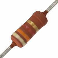
RES 4.3K OHM METAL FILM 2W 5%
Manufacturer
Vishay
Series
PR02r
Type
High power in small packagesr
Specifications of PR02000204301JR500
Resistance
4.3 KOhms
Power Rating
2 Watts
Voltage Rating
500 Volts
Temperature Coefficient
±250ppm/°C
Resistance (ohms)
4.3K
Power (watts)
2W
Composition
Metal Film
Features
Flame Retardant Coating
Tolerance
±5%
Size / Dimension
0.154" Dia x 0.472" L (3.90mm x 12.00mm)
Lead Style
Through Hole
Package / Case
Axial
Resistance In Ohms
4.30K
Case
Axial
Termination Style
Axial
Operating Temperature Range
- 55 C to + 175 C
Dimensions
3.9 mm Dia. x 10 mm L
Resistance Tolerance
± 5%
Resistor Element Material
Metal Film
Lead Free Status / RoHS Status
Lead free / RoHS Compliant
Height
-
Lead Free Status / Rohs Status
Lead free / RoHS Compliant
Other names
5083NW4K300J12AFX
PPC4.3KW-2TR
PPC4.3KW-2TR


PR01/02/03
Vishay BCcomponents
Ø 0.6 mm Cu-leads
Minimum distance from resistor body to PCB = 1 mm
Application Information
www.vishay.com
118
PR01 Temperature rise (ΔT) at the lead end (soldering point) as a
conditions; the data may deviate according to the applications.
conditions; the data may deviate according to the applications.
This graph is based on measured data under constant voltage
This graph is based on measured data under constant voltage
function of dissipated power at various lead lengths after mounting.
PR02 Time to interruption as a function of overload power
PR03 Time to interruption as a function of overload power
(K)
∆ T
(s)
(s)
10
10
10
10
t
t
100
10
10
-1
1
-1
1
80
60
40
20
2
2
0
0
0
0
for range: 0.68 R ≤ R
for range: 5 R ≤ R
20
50
40
0.4
100
60
150
n
For technical questions, contact:
n
< 68 R
80
0.8
≤ 560 R
P
P
overload
overload
Power Metal Film Leaded Resistors
200
P (W)
100
15 mm
25 mm
20 mm
(W)
(W)
120
250
1.2
filmresistorsleaded@vishay.com
Interruption Characteristics
Ø 0.6 mm Cu-leads
Ø 0.6 mm FeCu-leads
conditions; the data may deviate according to the applications.
This graph is based on measured data under constant voltage
PR02 Time to interruption as a function of overload power
PR01 Hot-spot temperature rise (ΔT) as a function
PR01 Hot-spot temperature rise (ΔT) as a function
∆ T
(K)
∆ T
(K)
10
(s)
10
t
200
160
120
10
200
160
120
-1
1
80
40
80
40
2
0
0
0
0
0
for range: 68 R ≤ R
20
of dissipated power.
of dissipated power.
40
0.4
0.4
60
n
80
≤ 560 R
0.8
Document Number: 28729
0.8
P
overload
100
P (W)
P (W)
Revision: 14-Oct-09
(W)
120
1.2
1.2
Related parts for PR02000204301JR500
Image
Part Number
Description
Manufacturer
Datasheet
Request
R

Part Number:
Description:
357-036-542-201 CARDEDGE 36POS DL .156 BLK LOPRO
Manufacturer:
Vishay
Datasheet:
Part Number:
Description:
357-036-542-201 CARDEDGE 36POS DL .156 BLK LOPRO
Manufacturer:
Vishay
Datasheet:
Part Number:
Description:
357-036-542-201 CARDEDGE 36POS DL .156 BLK LOPRO
Manufacturer:
Vishay
Datasheet:
Part Number:
Description:
357-036-542-201 CARDEDGE 36POS DL .156 BLK LOPRO
Manufacturer:
Vishay
Datasheet:
Part Number:
Description:
357-036-542-201 CARDEDGE 36POS DL .156 BLK LOPRO
Manufacturer:
Vishay
Datasheet:
Part Number:
Description:
357-036-542-201 CARDEDGE 36POS DL .156 BLK LOPRO
Manufacturer:
Vishay
Datasheet:
Part Number:
Description:
357-036-542-201 CARDEDGE 36POS DL .156 BLK LOPRO
Manufacturer:
Vishay
Datasheet:
Part Number:
Description:
357-036-542-201 CARDEDGE 36POS DL .156 BLK LOPRO
Manufacturer:
Vishay
Datasheet:
Part Number:
Description:
357-036-542-201 CARDEDGE 36POS DL .156 BLK LOPRO
Manufacturer:
Vishay
Datasheet:
Part Number:
Description:
357-036-542-201 CARDEDGE 36POS DL .156 BLK LOPRO
Manufacturer:
Vishay
Datasheet:
Part Number:
Description:
357-036-542-201 CARDEDGE 36POS DL .156 BLK LOPRO
Manufacturer:
Vishay
Datasheet:
Part Number:
Description:
357-036-542-201 CARDEDGE 36POS DL .156 BLK LOPRO
Manufacturer:
Vishay
Datasheet:
Part Number:
Description:
357-036-542-201 CARDEDGE 36POS DL .156 BLK LOPRO
Manufacturer:
Vishay
Datasheet:
Part Number:
Description:
357-036-542-201 CARDEDGE 36POS DL .156 BLK LOPRO
Manufacturer:
Vishay
Datasheet:
Part Number:
Description:
357-036-542-201 CARDEDGE 36POS DL .156 BLK LOPRO
Manufacturer:
Vishay
Datasheet: