SFR16S0005119FR500 Vishay, SFR16S0005119FR500 Datasheet - Page 3
SFR16S0005119FR500
Manufacturer Part Number
SFR16S0005119FR500
Description
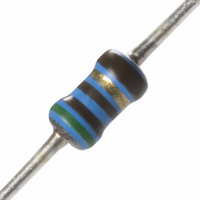
RES 51.1 OHM METAL FILM .50W 1%
Manufacturer
Vishay
Series
SFR16Sr
Type
Standard Metal Film Leaded Resistorsr
Datasheet
1.SFR2500001003FR500.pdf
(11 pages)
Specifications of SFR16S0005119FR500
Resistance (ohms)
51.1
Power (watts)
0.5W, 1/2W
Composition
Metal Film
Temperature Coefficient
±100ppm/°C
Tolerance
±1%
Size / Dimension
0.075" Dia x 0.161" L (1.90mm x 4.10mm)
Lead Style
Through Hole
Package / Case
Axial
Resistance In Ohms
51.1
Case
Axial
Resistance
51.1 Ohms
Power Rating
0.5 Watt (1/2 Watt)
Voltage Rating
200 Volts
Termination Style
Axial
Operating Temperature Range
- 55 C to + 125 C
Dimensions
1.9 mm Dia. x 3.5 mm L
Product
Metal Film Resistors Low Noise
Lead Free Status / RoHS Status
Lead free / RoHS Compliant
Features
-
Height
-
Lead Free Status / Rohs Status
Details
Other names
2306 187 15119
230618715119
5033ED51R10F12AF5
PPC51.1XTR
230618715119
5033ED51R10F12AF5
PPC51.1XTR


SFR16S/25/25H
Vishay BCcomponents
PRODUCTS WITH RADIAL LEADS (SFR25, SFR25H)
Note
• Please refer document number 28721 “Packaging” for more detail
www.vishay.com
36
MASS PER UNIT
TYPE
SFR16S
SFR25
SFR25H
DIMENSIONS - RADIAL TAPING
SYMBOL
P
P
P
P
F
W
W
H
H
H
D
L
L
1
0
1
2
1
0
0
0
H
1
Minimum lead wire (tape portion) shortest lead
Feed-hole centre to lead at topside at the tape
H
H
Height of component from tape center
0
Maximum length of snipped lead
Feed-hole center to body center
Minimum hold down tape width
L
For technical questions, contact:
L
1
Lead wire clinch height
Standard Metal Film Leaded Resistors
Lead-to-lead distance
Pitch of components
Feed-hole diameter
Component height
Feed-hole pitch
PARAMETER
MASS
(mg)
Tape width
102
205
205
F
P
2
P
0
P
filmresistorsleaded@vishay.com
P
1
OUTLINES
The length of the body (L
leads into holes of two identical gauge plates and moving
these plates parallel to each other until the resistor body is
clamped without deformation (IEC 60294).
MARKING
The nominal resistance and tolerance are marked on the
resistor using four or five colored bands in accordance with
IEC 60062, marking codes for resistors and capacitors.
D
VALUE
0
12.7
12.7
3.85
6.35
18.0
16.5
19.5
11.0
4.8
5.5
4.0
2.5
29
W
1
0
) is measured by inserting the
TOLERANCE
W
+ 0.7/- 0
± 1.0
± 0.2
± 0.5
± 1.0
± 0.5
± 0.5
± 0.2
Max.
Document Number: 28722
± 1
-
-
-
Revision: 06-Aug-10
UNIT
mm
mm
mm
mm
mm
mm
mm
mm
mm
mm
mm
mm
mm
Related parts for SFR16S0005119FR500
Image
Part Number
Description
Manufacturer
Datasheet
Request
R

Part Number:
Description:
357-036-542-201 CARDEDGE 36POS DL .156 BLK LOPRO
Manufacturer:
Vishay
Datasheet:
Part Number:
Description:
357-036-542-201 CARDEDGE 36POS DL .156 BLK LOPRO
Manufacturer:
Vishay
Datasheet:
Part Number:
Description:
357-036-542-201 CARDEDGE 36POS DL .156 BLK LOPRO
Manufacturer:
Vishay
Datasheet:
Part Number:
Description:
357-036-542-201 CARDEDGE 36POS DL .156 BLK LOPRO
Manufacturer:
Vishay
Datasheet:
Part Number:
Description:
357-036-542-201 CARDEDGE 36POS DL .156 BLK LOPRO
Manufacturer:
Vishay
Datasheet:
Part Number:
Description:
357-036-542-201 CARDEDGE 36POS DL .156 BLK LOPRO
Manufacturer:
Vishay
Datasheet:
Part Number:
Description:
357-036-542-201 CARDEDGE 36POS DL .156 BLK LOPRO
Manufacturer:
Vishay
Datasheet:
Part Number:
Description:
357-036-542-201 CARDEDGE 36POS DL .156 BLK LOPRO
Manufacturer:
Vishay
Datasheet:
Part Number:
Description:
357-036-542-201 CARDEDGE 36POS DL .156 BLK LOPRO
Manufacturer:
Vishay
Datasheet:
Part Number:
Description:
357-036-542-201 CARDEDGE 36POS DL .156 BLK LOPRO
Manufacturer:
Vishay
Datasheet:
Part Number:
Description:
357-036-542-201 CARDEDGE 36POS DL .156 BLK LOPRO
Manufacturer:
Vishay
Datasheet:
Part Number:
Description:
357-036-542-201 CARDEDGE 36POS DL .156 BLK LOPRO
Manufacturer:
Vishay
Datasheet:
Part Number:
Description:
357-036-542-201 CARDEDGE 36POS DL .156 BLK LOPRO
Manufacturer:
Vishay
Datasheet:
Part Number:
Description:
357-036-542-201 CARDEDGE 36POS DL .156 BLK LOPRO
Manufacturer:
Vishay
Datasheet:
Part Number:
Description:
357-036-542-201 CARDEDGE 36POS DL .156 BLK LOPRO
Manufacturer:
Vishay
Datasheet: