PCL712A Switchcraft Inc., PCL712A Datasheet
PCL712A
Manufacturer Part Number
PCL712A
Description
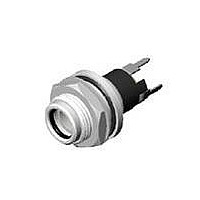
CONN JACK STR MINI POWER PCB
Manufacturer
Switchcraft Inc.
Specifications of PCL712A
Rohs Information
Switchcraft RoHS Info.
Connector Type
Jack
Gender
Male
Plug/mating Plug Diameter
2.5mm ID, 5.5mm OD
Number Of Positions/contacts
2 Conductors, 3 Contacts
Internal Switch(s)
Single Switch, Normally Closed
Mounting Type
Through Hole
Termination
Solder Eyelet(s)
Shielding
Unshielded
Features
Mounting Hardware, Thread Lock
Color
Silver
Product
Jacks
Inside Contact Diameter
2.5 mm
Current Rating
5 A
Voltage Rating
12 V
Mounting Angle
Straight
Mounting Style
Through Hole
Contact Material
Copper
Lead Free Status / RoHS Status
Contains lead / RoHS non-compliant
Lead Free Status / RoHS Status
Lead free / RoHS Compliant, Contains lead / RoHS non-compliant
Available stocks
Company
Part Number
Manufacturer
Quantity
Price
Company:

Part Number:
PCL712AS
Manufacturer:
COILCRAFT INC
Quantity:
9


SWITCHCRAFT, INC. 5555 N. Elston Ave. • Chicago, IL 60630
Single open circuit. (J1.)
Transfer circuit. (J5).
Single closed. Isolated
switching “make”
circuit. (J4-1A).
JACK SCHEMATICS
Circuit Types: Jacks normally have through circuits, shunt
circuits, and/or isolated switching circuits, either individually or
in various combinations. The chart below shows schematics of
39 common jacks - many more combinations are possible, but
these are the most commonly used. A basic description of the
switching action of each jack accompanies each schematic.
Military Identification: Military specifications covering phone
jacks use a special code to describe jack functions. Jack
schematic descriptions are coded J-1 through J-13 (as
appropriate) to coincide with Federal Item Identification
Guides for Supply Cataloging. One or more groups of suffix
numbers/letters identify isolated switching circuits used.
Suffixes identify the switching by industry recognized notation,
i.e., 1-A, 1-B, 1-C, 1-D, etc. See chart below.
Double open circuit.
Isolated switching–
separate “break” and
make circuits (J2-1A-1B).
Double open circuit.
Isolated switching–
separate “make”
circuits on both tip and
ring. (J2-2A).
Single closed circuit,
sleeve common. (J3).
Tip closed, ring
open. (J10).
Double closed
circuit. (J7).
Single closed circuit
Isolated switching
“break” circuit. (J4-1B).
Double closed circuit.
Isolated switching
“make” circuit on ring
spring. (J7-1A).
DIMENSIONS ARE FOR REFERENCE ONLY
Single closed circuit. (J4).
Tip closed, ring open
(common to sleeve). (J6).
Single closed circuit.
Isolated switching
transfer circuit. (J4-1C).
Single closed circuit–
“make” before
“break”. (J8).
Single closed circuit
plus “make” before
“break”. Isolated
switching–“make”
before “break”
circuit. (J8-1D).
NOTE: Number indicates the quantity of circuit - 2-A means 2, A circuits.
Terminals locations shown on jack schematics do not necessarily coincide
with physical locations on jacks. Not all circuit types available on all jacks.
Notation
1-C
1-D
1-A
1-B
(mm)
Inch
Double open circuit. (J2).
Single open circuit.
Isolated switching
“break” circuit. (J1-1B).
Double closed circuit.
Isolated switching
“break” circuit. (J7-1B).
Single open circuit.
Isolated switching
transfer circuit. (J1-1C).
Single open circuit.
Isolated switching–
separate transfer and
“make” circuits.
(J1-1A-1C).
One, SPST switching circuit. Also known as NO
(normally open) or “make” circuit.
One, SPST switching circuit. Also known as NC
(normally closed) or “break” circuit.
One, SPDT switching circuit. Also known as transfer
or “break” before “make” circuit.
One, SPDT switching circuit. Also known as “make”
before “break” circuit.
Meaning
Single open circuit.
Isolated switching
“make” circuit. (J1-1-A).
Double closed circuit,
ring common to
sleeve. (J13).
Double open circuit.
Isolated switching
transfer circuit. (J2-1C).
“make” circuit.
“break” circuit. Sleeve
(J4-1B).
Double open circuit.
Isolated switching
(J2-1A).
Single closed circuit.
Isolated switching
common to isolated
switching circuit throw.
Related parts for PCL712A
Image
Part Number
Description
Manufacturer
Datasheet
Request
R

Part Number:
Description:
CONN PLUG PHONE 1/4" 2POS RED
Manufacturer:
Switchcraft Inc.
Datasheet:

Part Number:
Description:
CONN PLUG 2-COND 1/4" PHONE SLD
Manufacturer:
Switchcraft Inc.
Datasheet:

Part Number:
Description:
CONN PLUG PHONE SILENT 2-COND
Manufacturer:
Switchcraft Inc.
Datasheet:

Part Number:
Description:
THICK PANEL/GOLD PLA
Manufacturer:
Switchcraft Inc.
Datasheet:

Part Number:
Description:
CONN JACK PHONE 1/4" 2POS CLOSED
Manufacturer:
Switchcraft Inc.
Datasheet:

Part Number:
Description:
CONN PHONE JACK 2COND 1/4" OPEN
Manufacturer:
Switchcraft Inc.
Datasheet:
Part Number:
Description:
CONN JACK PHONE 1/4" 2POS W/HDWR
Manufacturer:
Switchcraft Inc.
Datasheet:

Part Number:
Description:
CONN PLUG PHONE .206" 2POS BLACK
Manufacturer:
Switchcraft Inc.
Datasheet:
Part Number:
Description:
CONN PLUG PHONE 1/4" FLAT 2POS
Manufacturer:
Switchcraft Inc.
Datasheet:

Part Number:
Description:
CONN PLUG FLAT PHONE 1/4" 3-COND
Manufacturer:
Switchcraft Inc.
Datasheet:

Part Number:
Description:
PHONE T-JACK PANEL .25" STD SGL
Manufacturer:
Switchcraft Inc.
Datasheet:

Part Number:
Description:
CONN JACK PANEL 96POS W/O JACK
Manufacturer:
Switchcraft Inc.
Datasheet:
Part Number:
Description:
CONN PLUG PHONE .206" 3POS BLACK
Manufacturer:
Switchcraft Inc.
Datasheet:

Part Number:
Description:
CONN JACK 1/4" 3-COND IN-LINE
Manufacturer:
Switchcraft Inc.
Datasheet:

Part Number:
Description:
CONN PLUG AUDIO PHONE 3COND BLK
Manufacturer:
Switchcraft Inc.
Datasheet:
PCL712A Summary of contents
Page 1
JACK SCHEMATICS Circuit Types: Jacks normally have through circuits, shunt circuits, and/or isolated switching circuits, either individually or in various combinations. The chart below shows schematics of 39 common jacks - many more combinations are possible, but these are the ...
Page 2
JACK SCHEMATICS Single closed circuit. Tip closed; ring open Isolated switching– circuits. Isolated “make” before “break” switching–two “make” circuit. (J4-1D). circuits and one “break” circuit. (J10-2A-1B). Tip closed; ring closed Double closed circuit. circuits. Isolated Separate sleeve switching–“break” “break” circuit. ...