TEH100M25R0FE Ohmite, TEH100M25R0FE Datasheet
TEH100M25R0FE
Manufacturer Part Number
TEH100M25R0FE
Description
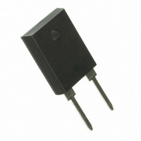
RES TK FM 25 OHM 100W 1% TO247
Manufacturer
Ohmite
Series
TEHr
Datasheet
1.TEH100M3R00JE.pdf
(1 pages)
Specifications of TEH100M25R0FE
Resistance (ohms)
25
Power (watts)
100W
Composition
Thick Film
Features
Non-Inductive
Temperature Coefficient
±50ppm/°C
Tolerance
±1%
Size / Dimension
0.630" L x 0.205" W (16.01mm x 5.21mm)
Height
0.825" (20.96mm)
Lead Style
Through Hole
Package / Case
TO-247-2
Resistance In Ohms
25.0
Case
TO-247
Resistance
25 Ohms
Power Rating
100 Watts
Termination Style
Radial
Voltage Rating
350 Volts
Operating Temperature Range
+ 25 C to + 175 C
Dimensions
16.01 mm W x 20.96 mm L x 2.21 mm H
Lead Spacing
10.42 mm
Product
Thick Film Resistors Leaded
Material, Element
Thick Film
Package Type
TO-247
Power, Rating
100 W
Termination
Radial
Lead Free Status / RoHS Status
Lead free / RoHS Compliant
(20.44~20.96mm)
64
TEH100 Series
100 Watt Thick Film Power
Resistors for High Frequency and
Pulse Loading Applications
(13.21~15.75mm)
0.05
0.075
0.1
0.2
0.5
1
2
2.5
3
5
7.5
10
15
20
25
50
100
470
750
1K
ohms
0.805~0.825"
0.520~0.620"
Ohmite Mfg. Co.
s T A n D A r D p A r T n u m b e r s F o r T e H s e r i e s
T E H 1 0 0 M 1 0 R 0 J E
Series
Check product availability at
(15.49~16.01mm)
o r D e r i n G i n F o r m A T i o n
(9.90~10.42mm)
TEH100MR050JE
TEH100MR075JE
TEH100MR100JE
TEH100MR200JE
TEH100MR500JE
TEH100M1R00JE
TEH100M2R00JE
TEH100M2R50JE
TEH100M3R00JE
TEH100M5R00JE
TEH100M7R50JE
TEH100M10R0JE
TEH100M15R0JE
TEH100M20R0JE
TEH100M25R0JE
TEH100M50R0JE
TEH100M100RJE
TEH100M470RJE
TEH100M750RJE
TEH100M1K00JE
0.610~0.630"
0.390~0.410"
5% tolerance
1600 Golf Rd., Rolling Meadows, IL 60008 • 1-866-9-OHMITE • Int’l 1-847-258-0300 • Fax 1-847-574-7522 • www.ohmite.com • info@ohmite.com
Package Code
M = two terminals
0.136~0.150"
(3.45~3.81mm)
0.054~0.066"
(1.37~1.67mm)
0.200~0.220"
(5.07~5.59mm)
ø0.139~0.147"
(3.53~3.73mm)
0.080~0.140"
(2.03~3.55mm)
www.ohmite.com
Ohms
R = Decimal
Example:
2R50 = 2.50Ω
25R0 = 25Ω
100R = 100Ω
1K00 = 1000Ω
TEH100M1R00FE
TEH100M2R00FE
TEH100M2R50FE
TEH100M3R00FE
TEH100M5R00FE
TEH100M7R50FE
TEH100M10R0FE
TEH100M15R0FE
TEH100M20R0FE
TEH100M25R0FE
TEH100M50R0FE
TEH100M100RFE
RoHS Compliant
Non-compliant
version unavailble
1% tolerance
(0.55~1.07mm)
using the Worldwide inventory
(2.15~2.67mm)
0.022~0.042"
Tolerance
F = 1%
J = 5%
0.085~0.105"
check product availability
search at ohmite.com
(4.69~5.21mm)
0.185~0.205"
Ohmite offers the totally encap-
sulated and insulated TO-247
package for low ohmic value
and non-inductive design for
high-frequency and pulsing
applications. Ideal use is for
power supplies. This series is
rated at 100 Watts mounted to
a heat sink.
F e A T u R e s
• 100 Watt power rating at 25°C
• Non-inductive performance
• Low thermal resistance
• RoHS compliant design
• TO-247 package configuration
• Single screw mounting simplifies
• A totally molded housing for envi-
• Non-Inductive design
• Resistor package totally insulated
D e R A T i n G
Derating (thermal resistance): 0.666W/°K (1.5K/W). Without a heatsink, when in
free air at 25°C, the TEH100 is rated for 3.5W. Derating for temp. above 25°C is
0.0234W/°K.
Graphed value is only valid when using a thermal conduction to the heatsink Rth-
cs<0.025°K/W. This value can be reached by using thermal transfer compound
with a heat conductivity of 1W/mK. The flatness of the cooling plate must be better
than 0.05mm overall. The roughness of the surface should not exceed 6.4µm. The
case temperature is to be used for the definitiion of the applied power limit. The
case temperature measurement must be made with a thermocouple contacting
the center of the component mounted on the designed heat sink. Thermal grease
should be applied properly
Test
Load life
Moisture
resistance
Short time
overload
Thermal shock GJB360A-96 method 107, Cond. F
Dielectric
strength
Terminal
strength
High frequency
vibration
case temperature
attach-ment to the heat sink
romental protection
from heat sink
100
Conditions Of Test
MIL-R-39009D 4.8.13 , 2,000 hours
at rated power
-10°C - +65°C, RH>90%, cycle 240 h ∆R ≤ ±(0.50% + 0.0005Ω)
1.5 times rated power and V(DC)
≤1.5Vmax for 5 seconds
GJB360A-96 method 301, (1,800V
AC, 60s)
GJB360A-96 method 211, Cond. A
(Pull Test) 2.4N
GJB360A-96 method 204, Cond. D
80
60
40
20
0
0
25
Bottom of base plate Temperature, °C
50
T e s T D A T A
75
s P e c i F i c A T i o n s
Material
Resistor: thick film on alumina
Case: high temperature plastic
Lead Material: Tinned Copper
Installation, max. Torque: 0.9 Nm
Electrical
Derating: linear, 100% at 25°C to
Resistance range: 0.05Ω to 1MΩ,
Resistance tol.: ±1%, ±2%, ±5%,
Max. working voltage: 350V
Temperature Coefficient:
Insulation Resistance: 10GΩ min.
Dielectric Strength: 1,800 VAC
using an M3 screw and a com-
pression washer
0% at 175°C
other values on request
±10%
±50ppm/°C for >10Ω, referenced
to 25°C,
others on request
100
125
∆
Performance
∆R ≤ ±(1.0% + 0.0005Ω)
∆R ≤ ± (0.50% + 0.0005Ω)
∆R ≤ ±(0.50% + 0.0005Ω)
∆R ≤ ± (0.15% + 0.0005Ω)
∆R ≤ ±(0.20% + 0.0005Ω)
∆R ≤ ±(0.40% + 0.0005Ω)
R taken at +105°C;
150
175
Related parts for TEH100M25R0FE
Image
Part Number
Description
Manufacturer
Datasheet
Request
R

Part Number:
Description:
RESISTOR POWER 1.0 OHM 50W
Manufacturer:
Ohmite
Datasheet:

Part Number:
Description:
POINTER BAR KNOB, 6.35MM
Manufacturer:
Ohmite
Datasheet:

Part Number:
Description:
HAND WHEEL POINTER KNOB, 9.525MM
Manufacturer:
Ohmite
Datasheet:

Part Number:
Description:
FINGER GRIP KNOB, 3.175MM
Manufacturer:
Ohmite
Datasheet:


Part Number:
Description:
MOUNTING CLIP, 90 SERIES RESISTOR
Manufacturer:
Ohmite
Datasheet:

Part Number:
Description:
ADJUSTABLE LUG FOR DIVIDOHM
Manufacturer:
Ohmite
Datasheet:
Part Number:
Description:
ADJUSTABLE LUG FOR DIVIDOHM
Manufacturer:
Ohmite
Datasheet:


Part Number:
Description:
RESISTOR POWER 1.0 OHM 50W
Manufacturer:
Ohmite
Datasheet:
Part Number:
Description:
HAND WHEEL POINTER KNOB, 9.525MM
Manufacturer:
Ohmite
Datasheet:
Part Number:
Description:
RHEOSTAT REPAIR KIT
Manufacturer:
Ohmite
Datasheet: