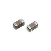
C1005X7R1C224K TDK Corporation, C1005X7R1C224K Datasheet - Page 127

C1005X7R1C224K
Manufacturer Part Number
C1005X7R1C224K
Description
CAP CER .22UF 16V X7R 10% 0402
Manufacturer
TDK Corporation
Series
Cr
Specifications of C1005X7R1C224K
Capacitance
0.22µF
Tolerance
±10%
Package / Case
0402 (1005 Metric)
Voltage - Rated
16V
Temperature Coefficient
X7R
Mounting Type
Surface Mount, MLCC
Operating Temperature
-55°C ~ 125°C
Features
Low ESR
Applications
General Purpose
Size / Dimension
0.039" L x 0.020" W (1.00mm x 0.50mm)
Thickness
0.50mm
Voltage Rating
16 Volts
Operating Temperature Range
- 55 C to + 125 C
Temperature Coefficient / Code
X7R
Product
General Type MLCCs
Dimensions
0.5 mm W x 1 mm L x 0.5 mm H
Termination Style
SMD/SMT
Lead Free Status / RoHS Status
Lead free / RoHS Compliant
Ratings
-
Lead Spacing
-
Lead Free Status / Rohs Status
Lead free / RoHS Compliant
Other names
445-5936-2
- Current page: 127 of 174
- Download datasheet (17Mb)
• All specifications are subject to change without notice. Please read the precautions before using the product.
PC Board
Features
Pattern
Temperature Characteristic
Rated Voltage (DC)
Series Name
Case Code
CKCL44
CKCA43
Temperature
Characteristics
C0G
X5R
X7R
Voltage Code
0J
1A
1C
1E
1H
Part Number
Construction
• Multiple capacitors are fitted in a single product,
contributing to reduced installation costs.
• The electrostatic capacity range and shape are
designed to meet the demands of the cellular phone
market.
• Reduced crosstalk (signal interference) between the
terminals.
Symbol CKCL44
A
B
C
P
Length
2.00 ± 0.15
3.20 ± 0.20
Capacitance
Change
0±30 ppm/ºC
±15%
±15%
Voltage(DC)
6.3V
10V
16V
25V
50V
P
0.55 mm
0.60 mm
0.25 mm
0.50 mm
Width
1.25 ± 0.15
1.60 ± 0.20
Temperature
Range
-55 to +125ºC
-55 to +85ºC
-55 to +125ºC
CKC Series
4 Elements Array Capacitors
CKCA43
0.6~0.7 mm
0.8~1.0 mm
0.30 mm
0.80 mm
Type: CKCL44 (C2012), CKCA43 (C3216)
CKCL44 X7R 1E 103 M T XXXX
Applications
Dimensions
Shape &
US Catalog // CKC Series — Array Type Capacitors // Version A10
Internal Codes
Packaging Style
Capacitance Tolerance
Nominal Capacitance (pF)
The capacitance is expressed in three digit codes
and in units of pico Farads (pF). The first and
second digits identify the first and second significant
figures of the capacitance. The third digit identifies
the multiplier. R designates a decimal point.
Packaging Code
T
Tolerance Code
F
K
M
Capacitance Code Capacitance
0R5
010
102
105
• Cellular telephone interface
• Interface cable circuit
• PC and peripherals
• CPU bus line
• High frequency circuit
• Noise bypass circuit
Symbol CKCL44 (C2012)
L
W
T
C
P
Dimensions in mm
2.00 ± 0.15
1.25 ± 0.15
1.00 max.
0.25 ± 0.10
0.50 ± 0.10
Style
Tape and Reel
Tolerance
± 1%
± 10%
± 20%
0.5pF
1pF
1,000pF (1nF)
1,000,000pF (1μF)
L
W Body Width
T
C Terminal Width
P Terminal Spacing
Body Length
Body Height
CKCA43 (C3216)
3.20 ± 0.20
1.60 ± 0.20
1.10 max.
0.40 ± 0.20
0.80 ± 0.20
Related parts for C1005X7R1C224K
Image
Part Number
Description
Manufacturer
Datasheet
Request
R

Part Number:
Description:
TDK DC to DC Converters, DC to AC Inverters
Manufacturer:
TDK Corporation
Datasheet:

Part Number:
Description:
TDK DC to DC Converters, DC to AC Inverters
Manufacturer:
TDK Corporation
Datasheet:


