STEVAL-CCA018V1 STMicroelectronics, STEVAL-CCA018V1 Datasheet - Page 7
STEVAL-CCA018V1
Manufacturer Part Number
STEVAL-CCA018V1
Description
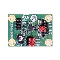
EVAL BOARD A/D TS4657
Manufacturer
STMicroelectronics
Type
Other Power Managementr
Datasheets
1.TS4657IQT.pdf
(26 pages)
2.STEVAL-CCA018V1.pdf
(12 pages)
3.STEVAL-CCA018V1.pdf
(4 pages)
Specifications of STEVAL-CCA018V1
Design Resources
STEVAL-CCA018V1 BOM STEVAL-CCA018V1 Schematic
Featured Product
STM32 Cortex-M3 Companion Products
Main Purpose
Audio, Audio Processing
Embedded
No
Utilized Ic / Part
TS4657
Primary Attributes
I²S, Right- or Left- Justified
Secondary Attributes
3 V ~ 5.5 V Supply
Interface Type
I2C
Operating Supply Voltage
3 V to 5.5 V
Product
Power Management Development Tools
Lead Free Status / RoHS Status
Lead free / RoHS Compliant
For Use With/related Products
TS4657
Other names
497-10735
Available stocks
Company
Part Number
Manufacturer
Quantity
Price
Company:

Part Number:
STEVAL-CCA018V1
Manufacturer:
STMicroelectronics
Quantity:
135


AN3001
3.4
3.5
Optional measurement loads
As shown in
on the demonstration board. These resistors are used to measure the performances of the
TS4657 with different loads. After the test, it is best to remove them and load the TS4657
with the application only.
The load on both outputs should be higher or equal to 5 k. Generally, the standard load for
the audio line is 10 k (10 K/1 %, 0.063 W, SMD resistors, 0603).
Specific considerations
The TS4657 utilizes a power management unit to supply its internal structures.
A self-generated negative supply allows the drivers to be powered from positive and
negative supplies, thus increasing the output signal amplitude. This internal negative supply
switches at a higher frequency than traditional architectures, derived from the master clock
MCLK. This structure uses an original design that allows suppressing the flying or floating
capacitors. Therefore, only four small 1 µF decoupling capacitors are necessary for
VCCA/VCCD and VREGA/VREGD.
Furthermore, the self-generated negative supply allows the amplifier outputs to be centered
around zero, thus the bulky output coupling capacitors can be removed.
As mentioned previously, the MCLK is used internally to supply some blocks. It is therefore
not recommended to switch off the MCLK during normal operation.
To properly power-down the device, MCLK, BCLK and LRCLK should be switched off after
the STDBY signal.
The power-down time is very short and can be considered as zero.
Figure 2 on page
Doc ID 15911 Rev 1
4, there are two resistors (R6 and R8) that are not connected
Configuring the demonstration board
7/12
Related parts for STEVAL-CCA018V1
Image
Part Number
Description
Manufacturer
Datasheet
Request
R

Part Number:
Description:
EVAL BOARD CC DRVR HI DENSE LEDS
Manufacturer:
STMicroelectronics
Datasheet:

Part Number:
Description:
EVAL BOARD CC DRVR HI DENSE LEDS
Manufacturer:
STMicroelectronics
Datasheet:

Part Number:
Description:
BATTERY CHARGER CELL PHONE
Manufacturer:
STMicroelectronics
Datasheet:

Part Number:
Description:
BOARD EVAL FOR MEMS SENSORS
Manufacturer:
STMicroelectronics
Datasheet:

Part Number:
Description:
KIT DEV STARTER ST10F276Z5
Manufacturer:
STMicroelectronics
Datasheet:

Part Number:
Description:
BOARD EVAL UPS 450W VOUT=220V
Manufacturer:
STMicroelectronics
Datasheet:

Part Number:
Description:
BOARD STLM75/STDS75/ST72F651
Manufacturer:
STMicroelectronics
Datasheet:

Part Number:
Description:
EVAL BOARD ENERGY METER MONO
Manufacturer:
STMicroelectronics
Datasheet:

Part Number:
Description:
EVAL BOARD ENERGY METER MONO
Manufacturer:
STMicroelectronics
Datasheet:

Part Number:
Description:
EVAL BOARD ENERGY METER MONO
Manufacturer:
STMicroelectronics
Datasheet:

Part Number:
Description:
STMicroelectronics [RIPPLE-CARRY BINARY COUNTER/DIVIDERS]
Manufacturer:
STMicroelectronics
Datasheet:
Part Number:
Description:
STMicroelectronics [LIQUID-CRYSTAL DISPLAY DRIVERS]
Manufacturer:
STMicroelectronics
Datasheet:
Part Number:
Description:
BOARD EVAL FOR MEMS SENSORS
Manufacturer:
STMicroelectronics
Datasheet: