STM32L152-EVAL STMicroelectronics, STM32L152-EVAL Datasheet - Page 43
STM32L152-EVAL
Manufacturer Part Number
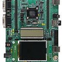
STM32L152-EVAL
Description
BOARD EVALUATION FOR STM32L
Manufacturer
STMicroelectronics
Type
MCUr
Specifications of STM32L152-EVAL
New! Us2012 Catalog Page
STM8L-Discovery_STM32L152-EVAL
Contents
Board
Processor To Be Evaluated
STM32L1xxx
Interface Type
UART
Operating Supply Voltage
2 V to 3.6 V
For Use With/related Products
STM32L
Lead Free Status / RoHS Status
Lead free / RoHS Compliant
Other names
497-10842


STM32L151xx, STM32L152xx
6.2
Absolute maximum ratings
Stresses above the absolute maximum ratings listed in
Table 7: Current
damage to the device. These are stress ratings only and functional operation of the device
at these conditions is not implied. Exposure to maximum rating conditions for extended
periods may affect device reliability.
Table 6.
1. All main power (V
2. Positive current injection is not possible on these I/Os. V
3. I
Table 7.
1. All main power (V
2. Negative injection disturbs the analog performance of the device. See note in
3. Positive current injection is not possible on these I/Os. V
4. A positive injection is induced by V
5. When several inputs are submitted to a current injection, the maximum I
|V
V
V
supply, in the permitted range.
must never be exceeded. A negative injection is induced by V
maximum is respected. If V
externally to the I
induced by V
supply, in the permitted range.
must never be exceeded. A negative injection is induced by V
must never be exceeded. Refer to
values.
positive and negative injected currents (instantaneous values). These results are based on
characterization with I
Symbol
SSX
I
INJ(PIN)
|V
ESD(HBM)
INJ(PIN)
I
DD
Symbol
V
INJ(PIN)
I
I
–V
VDD
DDx
VSS
I
IN
V
IO
SS
must never be exceeded (see
|
SS
(2)
|
Voltage characteristics
Current characteristics
IN
External main supply voltage
(including V
Input voltage on five-volt tolerant pin
Input voltage on any other pin
Variations between different V
Variations between all different ground pins
Electrostatic discharge voltage
(human body model)
< V
characteristics, and
Total current into V
Total current out of V
Output current sunk by any I/O and control pin
Output current sourced by any I/O and control pin
Injected current on five-volt tolerant I/O
Injected current on any other pin
Total injected current (sum of all I/O and control pins)
INJ(PIN)
DD
DD
SS
, V
, V
.
DDA
DDA
INJ(PIN)
value. A positive injection is induced by V
) and ground (V
) and ground (V
IN
DDA
maximum cannot be respected, the injection current must be limited
maximum current injection on four I/O port pins of the device.
and V
Doc ID 17659 Rev 4
IN
Table 6: Voltage characteristics
Ratings
> V
DD
Table 7: Current
DD
SS
DD
/V
Table 8: Thermal characteristics
)
SS
SS
(1)
DDA
ground lines (sink)
while a negative injection is induced by V
, V
, V
Ratings
SSA
SSA
(3)
power lines (source)
DD
) pins must always be connected to the external power
) pins must always be connected to the external power
power pins
(4)
(2)
characteristics). This is implicitly insured if V
IN
IN
maximum must always be respected. I
maximum must always be respected. I
(3)
IN
IN
<V
<V
(1)
Table 6: Voltage
SS
IN
SS
for the maximum allowed input voltage
> V
.
see
(1)
DD
V
V
INJ(PIN)
SS
SS
Section 6.3.10
–0.3
while a negative injection is
Min
(5)
Electrical characteristics
0.3
0.3
Section
is the absolute sum of the
may cause permanent
IN
characteristics,
6.3.15.
< V
V
+0 /-5
Max.
± 25
- 25
± 5
SS
DD
80
80
25
Max
4.0
4.0
50
50
. I
+4.0
INJ(PIN)
INJ(PIN)
INJ(PIN)
IN
Unit
43/107
mA
Unit
mV
V
Related parts for STM32L152-EVAL
Image
Part Number
Description
Manufacturer
Datasheet
Request
R

Part Number:
Description:
IAR� starter kit for STM32L EnergyLite 32-bit microcontrollers
Manufacturer:
STMICROELECTRONICS [STMicroelectronics]
Datasheet:

Part Number:
Description:
MCU, MPU & DSP Development Tools STM32L152VBT6 IAR 32KB Workbench
Manufacturer:
STMicroelectronics
Datasheet:

Part Number:
Description:
16/32-BITS MICROS
Manufacturer:
STMicroelectronics
Datasheet:
Part Number:
Description:
BOARD, EVAL, STM32L-DISCOVERY
Manufacturer:
STMicroelectronics
Datasheet:
Part Number:
Description:
STMicroelectronics [RIPPLE-CARRY BINARY COUNTER/DIVIDERS]
Manufacturer:
STMicroelectronics
Datasheet:
Part Number:
Description:
STMicroelectronics [LIQUID-CRYSTAL DISPLAY DRIVERS]
Manufacturer:
STMicroelectronics
Datasheet:

Part Number:
Description:
BOARD EVAL FOR MEMS SENSORS
Manufacturer:
STMicroelectronics
Datasheet:
Part Number:
Description:
NPN TRANSISTOR POWER MODULE
Manufacturer:
STMicroelectronics
Datasheet:
Part Number:
Description:
TURBOSWITCH ULTRA-FAST HIGH VOLTAGE DIODE
Manufacturer:
STMicroelectronics
Datasheet:
Part Number:
Description:
Manufacturer:
STMicroelectronics
Datasheet:
Part Number:
Description:
DIODE / SCR MODULE
Manufacturer:
STMicroelectronics
Datasheet:
Part Number:
Description:
DIODE / SCR MODULE
Manufacturer:
STMicroelectronics
Datasheet: