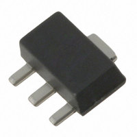
SKY65015-70LF Skyworks Solutions Inc, SKY65015-70LF Datasheet - Page 3

SKY65015-70LF
Manufacturer Part Number
SKY65015-70LF
Description
IC AMP INGAP LF-6GHZ SOT-89
Manufacturer
Skyworks Solutions Inc
Datasheet
1.SKY65015-70LF.pdf
(5 pages)
Specifications of SKY65015-70LF
Current - Supply
120mA
Frequency
0Hz ~ 6GHz
Gain
18dB
Noise Figure
4.2dB
P1db
17dBm
Package / Case
SOT-89
Rf Type
DBS, HLAN, WLAN
Test Frequency
2GHz
Voltage - Supply
5V
Lead Free Status / RoHS Status
Lead free / RoHS Compliant
Other names
863-1062-2
Available stocks
Company
Part Number
Manufacturer
Quantity
Price
Company:
Part Number:
SKY65015-70LF
Manufacturer:
Skyworks
Quantity:
1 400
Part Number:
SKY65015-70LF
Manufacturer:
SKYWORKS/思佳讯
Quantity:
20 000
Absolute Maximum Ratings
Performance is guaranteed only under the conditions listed in the specifications table and is
not guaranteed under the full range(s) described by the Absolute Maximum specifications.
Exceeding any of the absolute maximum/minimum specifications may result in permanent
damage to the device and will void the warranty.
CAUTION: Although this device is designed to be as robust as
SOT-89
RF input power
Supply voltage
Supply current
Power dissipation @ T = 25 °C
Operating temperature
Storage temperature
All measurements are in millimeters
7°
possible, Electrostatic Discharge (ESD) can damage
this device. This device must be protected at all times
from ESD. Static charges may easily produce poten-
tials of several kilovolts on the human body or
equipment, which can discharge without detection.
Industry-standard ESD precautions must be employed
at all times.
Characteristic
Side View
0.46
1.50
200356 Rev. D • Skyworks Proprietary Information • Products and Product Information are Subject to Change Without Notice. • February 21, 2007
Skyworks Solutions, Inc. • Phone [781] 376-3000 • Fax [781] 376-3100 • sales@skyworksinc.com • www.skyworksinc.com
Depth 0.100
Half Etching
3
R0.10
Bottom View
2
1
7°
R0.10
1.50 ± 0.10
0.381 ± 0.025
-65 °C to +125 °C
-40 °C to +85 °C
End View
500 mW
15 dBm
120 mA
Value
5 V
Sharp
Pin Out (Top View)
Pin Descriptions
Recommended Solder Reflow Profiles
Refer to the
Application Note.
Tape and Reel Information
Refer to the
Tape and Reel Package Orientation”
Pin Number
2, 4
1
3
“Discrete Devices and IC Switch/Attenuators
“Recommended Solder Reflow Profile”
Pin Name
Output
Input
GND
1
Equipotential point – Internal circuit com-
mon, which must be connected to the PCB
ground or common via the lowest possible
impedance. Pin 4 must be connected via a
low thermal resistance path to a good
heatsink.
RF input – RF input with 50 Ω nominal
input impedance. An internally generated
DC voltage is present at this pin, so an
external DC block should be used to
connect this pin to the external circuit.
RF output – DC supply voltage input and
RF output with 50 Ω nominal output
impedance. The nominal voltage required
at this pin is listed in the Electrical
Specifications Table. Supply current is
determined by an external resistor
connected between the DC power supply
and this pin.
4
2
DATA SHEET • SKY65015-70LF
Application Note.
3
Description
3


