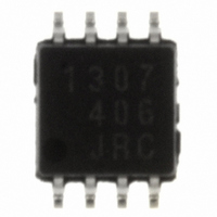
NJG1307R-TE1 NJR, NJG1307R-TE1 Datasheet - Page 4

NJG1307R-TE1
Manufacturer Part Number
NJG1307R-TE1
Description
IC MMIC DRIVER AMPLIFIER 8-VSP
Manufacturer
NJR
Datasheet
1.NJG1307R-TE1.pdf
(14 pages)
Specifications of NJG1307R-TE1
Current - Supply
25mA ~ 35mA
Frequency
800MHz, 1.5GHz, 1.9GHz
Gain
29dB ~ 33dB
P1db
10dBm
Package / Case
8-VSP
Rf Type
Cellular
Test Frequency
1.5GHz
Voltage - Supply
2.7V ~ 5V
Lead Free Status / RoHS Status
Contains lead / RoHS non-compliant
Noise Figure
-
Other names
NJG1307R-TE1TR
Available stocks
Company
Part Number
Manufacturer
Quantity
Price
Company:
Part Number:
NJG1307R-TE1
Manufacturer:
ROHM
Quantity:
100
Part Number:
NJG1307R-TE1
Manufacturer:
JRC
Quantity:
20 000
NJG1307R
nTERMINAL INFORMATION
- 4 -
No.
1
2
3
4
5
6
7
8
SYMBOL
GND1
GND2
GND1
RF
RF
V
RF
RF
CONT
out1
out2
in1
in2
RF signal output terminal from Wide-Band variable gain
Amplifier. And this terminal is also the voltage supply terminal
of wide-band variable gain amplifier, therefore should be
supplied voltage through the choke coil.
Voltage input terminal or gain control circuit.
Ground terminal. No.3 and No.7 pins connected inside IC.
RF signal input terminal to wide-band variable gain amplifier.
RF signal output terminal from driver amplifier. And this
terminal is also the voltage supply terminal of driver amplifier,
therefore should be supplied voltage through the choke coil.
Ground terminal.
However GND1 terminal must not be connected to GND2,
please use different through hole to connect ground plane.
(Please see RECOMMENDED PCB DESIGN)
Ground terminal.
RF signal input terminal to driver amplifier.
DESCRIPTIONS


